OPERATION
The internally stored parameters used by the controller during op-
eration can be changed using STA60M or STA70M sensor or using
a Supervisory System (MODBUS protocol). Remote Sensor NR9000-RT
allows to change the operation mode, the set point and the fan
speed; all other parameters can be modified only through the su
-
pervisory system or the dedicated configuration tool. The controller
can operate also without the Remote Sensor using a dedicated an-
alogue input (Return Sensor).
The controller will consider the data acquired by the Sensor and by
the Supervisory system (if present) and will perform a P or PI or PID
regulation to drive the valves and the fan.
The controller can operate also without NR9000-RT and supervisory
system (Modbus). In this case the room temperature is measured by
the return sensor and thanks to the remote selector it is possible to set
the correction of the temperature. In this configuration, the control
parameters can be changed only through a dedicated configura
-
tion tool.
System configuration
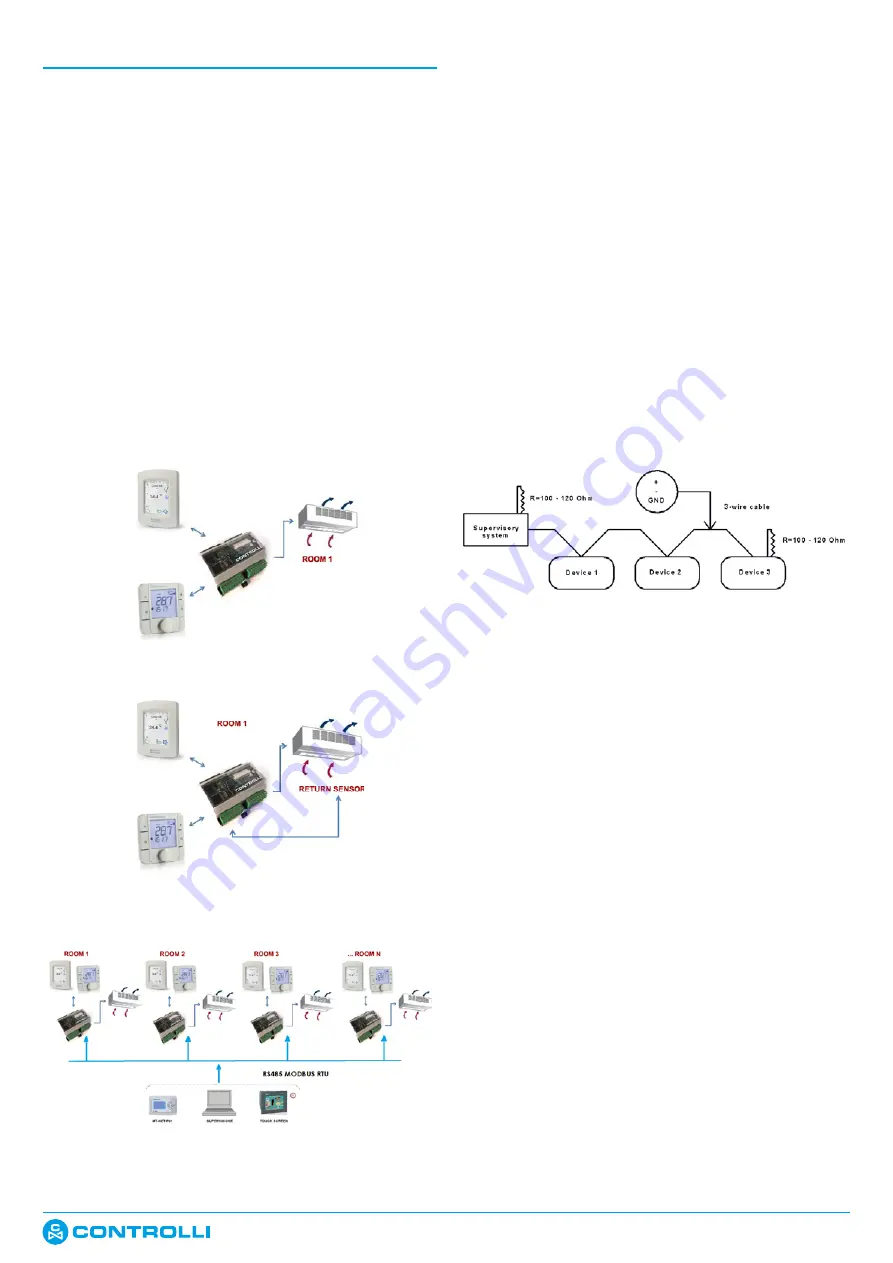
The system can be configured as shown in the following diagrams:
•
Cont Remote sensor
•
Controller (Stand Alone) with return sensor
•
N Contr N Remote s Supervisor
Supervisory system
•
Operator Panel: MT-NET-PONR: it is possible to connect up to 50
controllers.
•
PC Supervisor: configuration tool “Configuratore NR9000” down
-
loadable from www.controlli.eu site; in this case it is possible to
connect up to 250 controllers. It is possible to use also Micronet
View or Touch Screen GTO series on demand getting in touch
with our technical dept.; in this case it is possible to connect up
to 48 controllers.
ModBus - RS485 Connection
The RS485 network is implemented with a 3-conductor cable, which
will be later identified as “+” (pin 23), “-” (pin 24) and “GND” (pin 25).
For wiring is suggested Belden®, model 8762.
For “disturbed” areas is suggested a Belden®, model 3106A using the
twisted pair to connect the “+” and “-“, the reference wire to con-
nect to “GND” and the shield to connect to ground.
Alternatively you can use a cable with the following electrical and
mechanical characteristics:
•
AWG 20/22;
•
characteristic impedance of 120Ω;
•
copper wire, “plait” type, twisted;
•
shielded braided and insulated;
The shield must be connected to controller GND (pin 25).
The network must be wired only in accordance with the principle
shown here, called “daisy chain” (the device is composed by a sin
-
gle RS485 port). Star connections are not allowed.
Connections warnings
1.
Do not use different types of cable to achieve the same net
-
work, but always use only the same type of cable;
2.
The network cable carries out safety voltage signals (SELV) and
must not be wired together with dangerous voltage signals
(e.g., 230Vac) or carriers of high currents, especially if in alter-
nating current. Also avoid parallel paths to these power cables;
3.
Wire the cable lying avoiding kinks, narrow bending radii and
unnecessary wrapping in hanks or skeins;
4. Do not twist the cable cord around the power conductors and,
if they should cross, consider an intersection at 90 ° between the
cable and these conductors;
5.
Keep away from sources of electromagnetic field in particular
by large motors, electrical cabinet, reactors for neon, all types
of antennas;
6.
Do not pull the power cable exceeds 110N (11.3kg) to prevent
ironing;
7.
Assess in advance the route so that it will be as short as possible
and note addresses of connected instruments with particular
reference to its location in the orderly sequence. This can be
very useful in maintenance; we recommend to note the Mod
-
bus Address on the product label.
8.
Do not reverse the polarity “+” and “-” of the connection ter
-
minals;
9.
Avoid short lengths of cable terminations in connection tools
to make a maintenance without tearing or flues of the cables
possible;
10.
Identify start and ending terminations and avoid cuts “open”;
Terminating resistors and network polarization
The slew rate control, mutual function in our 485 transceiver and the
limited baud rate to 9600 baud make the terminating resistors not
necessary.
RS485 network needs of polarization typically in charge of the master
device; the controller doesn’t have polarization resistors.
The transceiver used by the controller allows to drive up to 256 points.
RS485 standards require a maximum length of 1200m and/or 32 de-
vices on the network.
It should be noted that more limits are exceeded, higher is the prob-
ability that problems in communication arise. The phenomenon is not
1
st
Issue
06/2019
DBL585e
Page 8


