background image

12

Option 4: 

STS-S61 Flush Mounted Speaker (Wall/Counter Installations)

1. 

Ensure there is at least 2 inches of free space below the customer side of 

the countertop for the speaker pod.


2.  Ensure there is access to the wiring under the counter once installed.


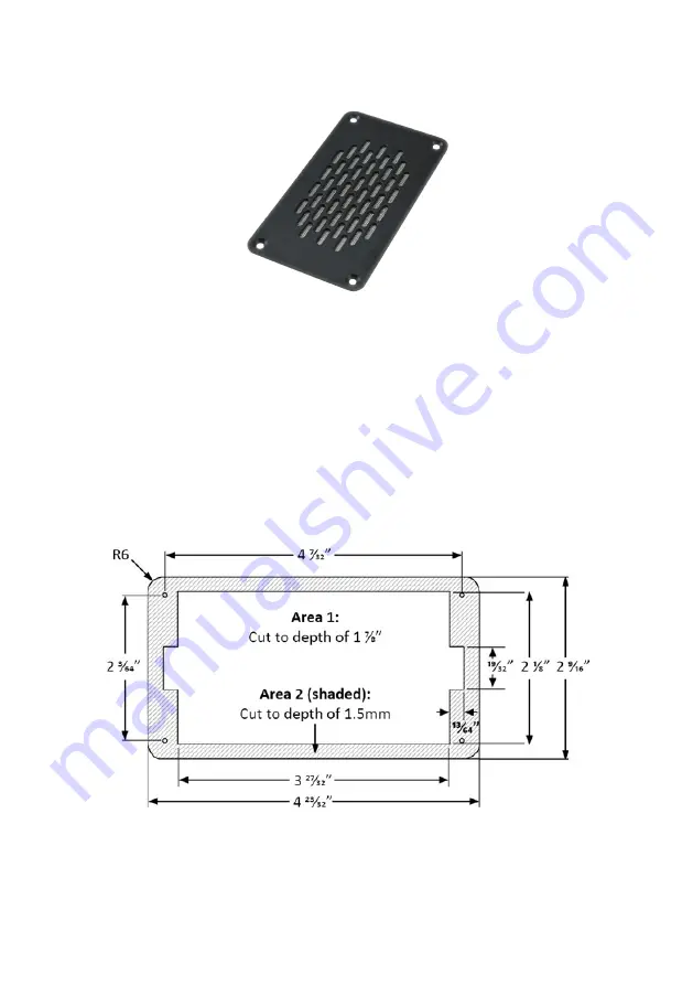
3.  Mark the cut-out dimensions in the diagram below onto the countertop.


4.  Use a router to cut out two areas for the flush mounted speaker pod.


5.  Cut Area 1 in diagram to a depth of 1 7⁄8”.


6.  Cut Area 2 (shaded) in diagram to a depth of 1.5mm.


7.  Cut corner radius to R6 in Area 2.

Summary of Contents for STS-K020

Page 1: ...Speech Transfer System STS K020 December 2019 Installation User Guide ...

Page 2: ...ker Microphone Installation Hearing Loop Installation Amplifier Setup Using the System Troubleshooting 3 4 5 7 14 18 21 25 27 Contacta has a policy of continuous product development and therefore small specification changes may not be reflected in this manual Images labels packaging accessories and product colors are subject to change without notice ...

Page 3: ...duct is designed for installation at locations such as banks post offices theaters and more A hearing loop aerial is included to provide additional assistance for hearing device wearers Features Excellent sound quality ADA conscious Level 3 ballistic rated Sleek and modern design Product Overview ...

Page 4: ...er ensuring that it will not obstruct staff when they are sitting Fixing points 2 Take note of the cable management path 3 Mark the four fixing points for the amplifier under the counter 4 Drill and fix the amplifier in place using the supplied screws 5 Please take note of the cable management path at this time ...

Page 5: ...he opening of the glass barrier 5 Hold the front polycarbonate plate flush to the opening in the glass barrier and use tape to temporary secure the front polycarbonate plate to the window 6 Move to the staff side Feed the second silicon gasket through the wire and align the holes to slip onto the studs 7 Determine the direction needed for the wire tubing vertical or horizontal Align the plates acc...

Page 6: ... the alignment studs and replace with the remaining three 8 32 2 screws 13 Tighten the screws in a star configuration tightening each screw in small increments until all screws are completely tightened 14 Secure the tubing in place 15 Plug the wire s connector into the Cust Mic port on the back of the amplifier Note The RED wire should be on the RIGHT side of the connector ...

Page 7: ... the material 4 Check the cable route to the amplifier location under the counter noting cable length and access through the countertop 5 Mark the fixing points to mount the back plate while ensuring there is access to retrieve the cable 6 Drill fixing points using a drill bit smaller in diameter than the screws that will be permanently installed 7 Align the back plate with the fixing points Ensur...

Page 8: ...8 11 Plug the speakers connector into the Cust Spkr port on the back of the amplifier ...

Page 9: ...t while ensuring there is access to retrieve the cable 4 Drill fixing points using a drill bit smaller in diameter than the screws that will be permanently installed 5 Align the speaker bracket with the fixing points 6 Mount the back plate using the appropriate screws fixings 7 With the cable facing down slip the bolts on the side of the speaker into the groves of the bracket Adjust position of sp...

Page 10: ...f interaction between the staff and customer at least 2 3mm away from the glass barrier 5 Mark two fixing points and one cable management hole to mount the housing bracket while ensuring there is access to retrieve the cable 6 Drill fixing points using a drill bit smaller in diameter than the screws that will be permanently installed then drill the hole for the speaker cable Housing fixing points ...

Page 11: ...peaker housing to the bracket with the previously removed screws 9 Route all cabling neatly to the amplifier location on the staff side 10 Plug the speakers connector into the Cust Spkr port on the back of the amplifier ...

Page 12: ...for the speaker pod 2 Ensure there is access to the wiring under the counter once installed 3 Mark the cut out dimensions in the diagram below onto the countertop 4 Use a router to cut out two areas for the flush mounted speaker pod 5 Cut Area 1 in diagram to a depth of 1 7 8 6 Cut Area 2 shaded in diagram to a depth of 1 5mm 7 Cut corner radius to R6 in Area 2 ...

Page 13: ...nently installed 10 Run the cable from the speaker through the countertop 11 Secure speaker to the counter using the screws provided Drilled fixing points Speaker pod container cut out Fixing points 12 Route all the cabling neatly to the amplifier location on the staff side 13 Plug the speakers connector into the Cust Spkr port on the back of the amplifier ...

Page 14: ... drill one or at least a inch hole in a suitable location near the rear of the counter 3 Plug the unit s connectors with BLACK and YELLOW wires into the Staff Spkr port on the back of the amplifier Note The BLACK wire should be on the LEFT side of the connector The YELLOW wire should be on the RIGHT side of the connector 4 Plug the unit s connectors with BLACK WHITE and RED wires into the Staff Mi...

Page 15: ...15 5 The staff unit can be turned on by flipping the switch When pressed down the O position indicates the unit is OFF and the I position indicates the unit is ON ...

Page 16: ...orresponding ports 5 To use the headphone and microphone ensure the mute button on the 1 The Break Out Box should be installed underneath the counter using the screws provided Ensure it is placed in a convenient location for the staff to access the mute button while being mindful of the headset cable length and the position of the staff member 2 Plug the unit s connectors with BLACK and YELLOW wir...

Page 17: ...ak Out Box Note The BLACK wire should be on the LEFT side of the connector The YELLOW wire should be on the RIGHT side of the connector b Plug the staff units connectors with BLACK WHITE and RED wires into the MIC port on the side of the Break Out Box Note The BLACK WHITE wires should be on the LEFT side of the connector The RED wire should be on the RIGHT side of the connector c To use the STS SU...

Page 18: ...not exceed 2 feet above the average standing customer 2 Clean the area with a glass cleaner and thoroughly wipe dry 3 Remove the liner on the blue sheet with a faint outline of the international hearing loop signage to expose the adhesive backing Please note that both sheets are not solid blue 4 Carefully attach the sheet on the glass barrier with the international hearing loop signage facing the ...

Page 19: ...coming from the back side of the aerial when applied 7 Attach the solid blue sheet with hearing loop aerial to the sheet attached to the glass barrier Slowly apply while smoothing out air bubbles with straight edged tool 8 Route the cabling neatly to the amplifier location on the staff side 9 Plug the loop s connector into the Loop port on the back of the amplifier ...

Page 20: ...r the counter using either the provided P clips or another fixing method of choice See the diagram below for recommended positioning A is the optimum layout for a counter hearing loop B and C are acceptable only if A is not possible and the layout is aligned so that the magnetic field will be directed towards user s head heights 2 Route the cabling neatly to the amplifier location on the staff sid...

Page 21: ...providing the best performance possible Note Ducking Adjustment and Hearing Loop Drive Adjustment should be kept at factory default levels see page 26 in the majority of circumstances If adjustments to either setting are required please seek consultation from Contacta s technical department Maximum Volume Adjustment Adjust the maximum volume level the amplifier delivers to both customer and staff ...

Page 22: ...justed so that red LED 8 on Vol Out is illuminated only when there are peaks in the speech volume see diagram on following page Entering Engineer s Mode Before entering engineer s mode cycle the power To do this either Switch the power off at the wall socket and back on again or Remove the power connector and re insert it To enter engineer s mode simultaneously press and press and quickly release ...

Page 23: ... there are 3 editable setup areas You will always enter setup area 1 first The adjustable setup modes are indicated by the green Volume In LED bar which will flash to indicate which setup area is active Maximum Volume Adjustment 1 Ducking Adjustment 2 and Hearing Loop Drive Adjustment 3 Setup Area 2 Ducking Adjustment Vol In LED 2 flashes Setup Area 1 Maximum Volume Adjustment Vol In LED 1 flashes...

Page 24: ...he pro cess Press the on off button to save and exit engineer s mode Please note that the amplifier will automatically exit Engineer s Mode without saving if no buttons are pressed for 2 minutes For best performance 1 Enter Setup Area 1 2 Ensure the customer and staff volumes are turned completely down 3 Adjust staff volume Volume In to a comfortable level 4 Increase customer volume Volume Out unt...

Page 25: ...ase the level The corresponding LED bar will show the volume setting To adjust the customer volume level Press and hold the Volume Out or buttons to increase or decrease the level The corresponding LED bar will show the volume setting Fault Diagnosis LEDs Volume In LED 8 will stay red if there is a fault with the staff microphone Volume Out LED 8 will stay red if there is a fault with the customer...

Page 26: ... and then reconnect it 2 Press the On Off button and Volume In button together then quickly release 3 The Volume In LED bar will have all LEDs illuminated while the Volume Out LED bar will display the firmware revision number in a fixed pattern of LEDs This indicates that default settings have been restored ...

Page 27: ...ions and if possible check the hearing device with a known working hearing loop 2 Ensure loop tester has a new set of batteries I can hear interference through speakers buzzing whistling hissing 1 Unscreened or poorly earthed third party equipment is being used in close proximity 2 Internal volume gain set to high 3 Incorrect power supply being used 1 Switch off any third party equipment to identi...

Page 28: ...Local dealer US Canada 1 616 392 3400 info contactainc com contactainc com ...

Reviews: