8. Remove impeller from shaft, being careful
not to lose the impeller key, spring and
gasket. If impeller is difficult to remove, it
may be necessary to use a bearing puller to
remove.
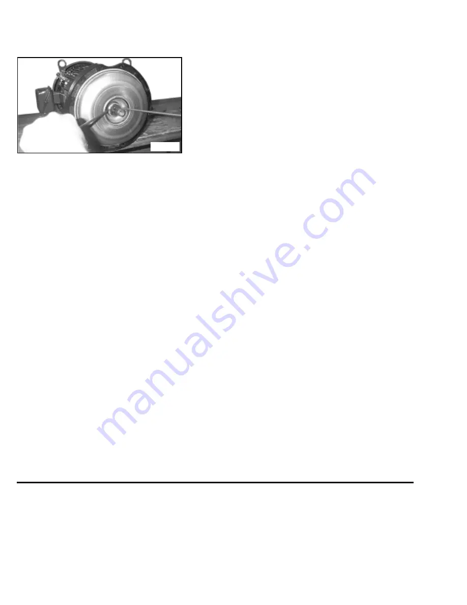
9. Pry off rotating member of mechanical seal
from sleeve by using two (2) screwdrivers.
Be careful not to damage the pump
cover. See Figure 5.
10. Remove pump cover from cast iron disc.
(There isn’t any hardware used to attach
cover to disc. Place cover on flat surface
with convex side down, and push out
stationary member of mechanical seal. It is
not necessary to remove cast iron disc from
motor to replace seal.
11. Inspect shaft sleeve and nylon washers. If
damaged or worn, remove from shaft and
replace.
A.) Reassembly:
CAUTION: The mechanical seal is a
precision product and should be handled
accordingly. Use care when handling lapped
running surfaces of the mechanical seal to
ensure they remain clean and are free of
chips or scratches.
1. Clean gasket and flange faces, seal seat
cavity, shaft sleeve, and motor shaft.
2. Position cover so that the convex side is
facing you. Lubricate the seal seat cavity of
the cover and the rubber cup or O-ring of
seal seat with the lubricating fluid that
comes with the mechanical seal or repair kit.
Press the stationary seat in seal seat cavity
of the cover squarely and evenly using a
arbor press (if possible) and the cardboard
disc supplied with the seal. Be certain that
the lapped face (shiny side) is facing you.
3. Install nylon washer on motor shaft until
it bottoms on the motor shaft.
4. Install sleeve on motor shaft.
5. Position the cover so that the convex side is
facing you and install on cast iron motor
disc. (There isn’t any hardward required to
attach cover to motor disc.)
6. Apply the lubricating fluid that comes with
the mechanical seal or repair kit to the motor
sleeve and the rubber bellows of the rotary
seal. Slide the seal head on the shaft sleeve,
press the rubber drive band on the rotary
head until the lapped face on the head seats
firmly against the lapped face of the
stationary seat. Do not chip or scratch faces
during installation. Take extra care to make
sure the lapped faces are clean.
7. Install nylon washer on shaft sleeve and seal
spring on seal head.
8. Place key in key seat. Line up keyway in
impeller with key on motor shaft, and slide
impeller on motor shaft. Be certain that the
key is positioned in the keyway of the motor
and impeller. Slightly compress seal spring
with impeller (making sure the seal spring is
positioned over stud on back of impeller),
and hold impeller while installing impeller
retaining assembly in motor shaft. Make
sure the nylon washer is installed on retain-
ing nut.
9. Insert a screwdriver in a waterway passage
of the impeller holding it against rotation
and tighten impeller retaining assembly as
discussed in paragraph 7.
10. Remove any burrs caused by screwdriver on
the vane of impeller in waterway passage.
11. Slide motor and rotating element in casing.
Be sure that any damaged O-ring or gasket
is replaced.
12. Tighten casing bolts alternately and evenly.
13. Replace hold-down bolts.
14. Check for free rotation after assembly is
completed.
15. Close all drain openings, using pipe sealant
on threads.
16. Reprime before starting. Do not start unit
until pump is completely filled with water.
The approved lubricating fluid for seal
installation is included with the mechanical
seal or repair kit. DO NOT USE OTHER
LUBRICATING LIQUIDS!
WE RECOMMEND STOCKING A SPARE
MECHANICAL SEAL OR REPAIR KIT
TO ELIMINATE DOWN TIME.
PRESSURE AND TEMPERATURE LIMITATION
STANDARD FITTED PUMPS
PUMP
PRESSURE
TEMPERATURE
NO.
STANDARD
OPTIONAL
STANDARD
OPTIONAL
68, 69
75 PSI
N/A
220°F
275°F
51, 61, 74
75 PSI
150 PSI
220°F
275°F
71, 72, 77, 78, 79, 82
75 PSI
N/A
220°F
275°F
11, 13, 60
75 PSI
150 PSI
220°F
275°F
62
165 PSI
165 PSI
220°F
275°F
ALL OTHERS
175 PSI
175 PSI
220°F
275°F
N/A-NOT AVAILABLE
CAUTION
DO NOT ALLOW EITHER THE DISCHARGE PRESSURE OR THE TEMPERATURE OF THE LIQUID TO
EXCEED THE LIMITATIONS LISTED ABOVE.
Figure 5


