background image

 19

Chapter 5


Advanced Setup   

This chapter explains the following screens: 


5.1 ETH WAN INTERFACE   

5.2 WAN 

5.3 LAN 

5.4 NAT 

5.5 Security 

5.6 Parental Control 

5.7 Routing 

5.8 DNS 

5.9 UPnP 

5.10 Interface Grouping 

5.11 Certificate 

5.1


ETH WAN INTERFACE 

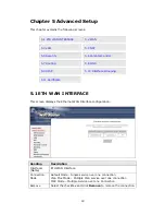
This screen displays the Ethernet WAN Interface configuration. 


Heading 

Description 

Interface/ 
(Name) 

ETH WAN Interface 

Connection 

Mode 

Default Mode – Single service over one connection 

Vlan Mux Mode – Multiple Vlan service over one connection 
MSC Mode – Multiple Service over one Connection 

Remove 

Select the checkbox and click 

Remove 

to remove the connection. 


Summary of Contents for WAP-5813n

Page 1: ...WAP 5813n Gigabit Wireless Router User Manual Version C1 0 May 20 2009 260097 001 ...

Page 2: ...s should be placed on the cord In addition do not walk on step on or mistreat the cord Use only the power cord and adapter that are shipped with this device To safeguard the equipment against overheating make sure that all openings in the unit that offer exposure to air are not blocked Avoid using a telephone other than a cordless type during an electrical storm There may be a remote risk of elect...

Page 3: ...e The cardboard box the plastic contained in the packaging and the parts that make up this router can be recycled in accordance with regionally established regulations Never dispose of this electronic equipment along with your household waste you may be subject to penalties or sanctions under the law Instead please be responsible and ask for disposal instructions from your local government ...

Page 4: ...INTERFACE 19 5 2 WAN 20 5 3 LAN 20 5 4 NAT 23 5 4 1 Virtual Servers 23 5 4 2 Port Triggering 25 5 4 3 DMZ Host 26 5 5 SECURITY 27 5 5 1 IP Filtering 27 5 5 2 MAC Filtering 30 5 6 PARENTAL CONTROL 31 5 6 1 Time Restriction 31 5 6 2 URL Filter 32 5 7 ROUTING 33 5 7 1 Default Gateway 33 5 7 2 Static Route 34 5 7 3 RIP 35 5 8 DNS 35 5 8 1 DNS Server 35 5 8 2 Dynamic DNS 36 5 9 UPNP 38 5 10 INTERFACE G...

Page 5: ...re Default 59 8 2 SYSTEM LOG 60 8 3 TR 069 CLIENT 61 8 4 INTERNET TIME 63 8 5 ACCESS CONTROL 63 8 5 1 Passwords 63 8 6 UPDATE SOFTWARE 64 8 7 SAVE AND REBOOT 65 APPENDIX A FIREWALL 66 APPENDIX B PIN ASSIGNMENTS 69 APPENDIX C SPECIFICATIONS 70 APPENDIX D SSH CLIENT 72 APPENDIX E WSC EXTERNAL REGISTRAR 73 ...

Page 6: ...ns and increased range without sacrificing compatibility with older wireless devices WPS Wi Fi Protected Setup and Wi Fi On Off buttons are included for easy wireless network setup WPA data encryption Firewall and VPN passthrough options are provided for state of the art network security 1 1 Features Integrated 802 11n AP 802 11b g backward compatible WPA WPA2 and 802 1x WMM UPnP RADIUS client IP ...

Page 7: ...Before servicing or disassembling this equipment disconnect all power cords and telephone lines from their outlets Reset Button Restore the default parameters of the device by pressing the Reset button for 5 to 10 seconds After the device has rebooted successfully the front panel should display as expected see section 2 2 LED Indicators for details NOTE If pressed down for more than 20 seconds the...

Page 8: ...left of the front panel as shown WI FI BUTTON Press this button to enable disable the wireless LAN WLAN WPS BUTTON Press this button to begin searching for WPS clients These clients must also enable WPS push button mode When WPS is available the WPS LED will be ON ...

Page 9: ...ink Data transmitting or receiving over Ethernet WAN On IP connected and no traffic detected If an IP or PPPoE session is dropped due to an idle timeout the light will remain green if an ADSL connection is still present Off Modem power off modem in bridged mode or ADSL connection not present In addition if an IP or PPPoE session is dropped for any reason other than an idle timeout the light is tur...

Page 10: ...PPoE IP over Ethernet IPoW Bridging The following connections are configured by default Interface Type Vlan Tag Vlan Mux IGMP NAT FIREWALL eth0 3 IPoW 4 3 N Y N ppp0 6 PPPoE 1 6 N Y Y Technical Note During power on the device initializes all settings to default values It will then read the configuration profile from the permanent storage section of flash memory The default attributes are overwritt...

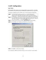
Page 11: ...s involved are similar for most operating systems OS Check your OS support documentation for further details STEP 1 From the Network Connections window open Local Area Connection You may also access this screen by double clicking the Local Area Connection icon on your taskbar Click the Properties button STEP 2 Select Internet Protocol TCP IP and click the Properties button STEP 3 Select Obtain an ...

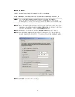
Page 12: ...eck your OS support documentation for further details STEP 1 From the Network Connections window open Local Area Connection You may also access this screen by double clicking the Local Area Connection icon on your taskbar Click the Properties button STEP 2 Select Internet Protocol TCP IP and click the Properties button STEP 3 Change the IP address to the domain of 192 168 1 x 1 x 255 with subnet m...

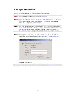
Page 13: ... http 192 168 1 1 NOTE For local administration i e LAN access the PC running the browser must be attached to the Ethernet and not necessarily to the device For remote access i e WAN use the IP address shown on the Device Information screen and login with remote username and password STEP 2 A dialog box will appear such as the one below Enter the default username and password as defined in section...

Page 14: ...13 STEP 3 After successfully logging in for the first time you will reach this screen ...

Page 15: ...red connection s and user account privileges For example if NAT and Firewall are enabled the main menu will display the NAT and Security submenus If either is disabled their corresponding menu s will also be disabled Device Info is the first selection on the main menu so it will be discussed first Subsequent chapters will introduce the other main menu options in sequence The Device Info Summary sc...

Page 16: ...ows the connection type VlanMuxId Shows 802 1Q VLAN ID IGMP Shows Internet Group Management Protocol IGMP status NAT Shows Network Address Translation NAT status Firewall Shows the status of Firewall Status Lists the status of DSL link IPv4 Address Shows WAN IPv4 address 4 2 Statistics This selection provides LAN WAN ATM and ADSL statistics NOTE These screens are updated every 15 seconds ...

Page 17: ...AN interface Heading Description Interface LAN interface s Received Transmitted Bytes Pkts Errs Drops Number of Bytes Number of Packets Number of packets with errors Number of dropped packets 4 2 2 WAN Statistics This screen shows data traffic statistics for each WAN interface ...

Page 18: ...nation Destination network or destination host Gateway Next hub IP address Subnet Mask Subnet Mask of Destination Flag U route is up reject route G use gateway H target is a host R reinstate route for dynamic routing D dynamically installed by daemon or redirect M modified from routing daemon or redirect Metric The distance to the target usually counted in hops It is not used by recent kernels but...

Page 19: ...Address Shows the MAC address of host pc Device Shows the connection interface 4 5 DHCP Click DHCP to display all DHCP Leases Field Description Hostname Shows the device host PC network name MAC Address Shows the Ethernet MAC address of the device host PC IP Address Shows IP address of device host PC Expires In Shows how much time is left for each DHCP Lease ...

Page 20: ...Grouping 5 11 Certificate 5 1 ETH WAN INTERFACE This screen displays the Ethernet WAN Interface configuration Heading Description Interface Name ETH WAN Interface Connection Mode Default Mode Single service over one connection Vlan Mux Mode Multiple Vlan service over one connection MSC Mode Multiple Service over one Connection Remove Select the checkbox and click Remove to remove the connection ...

Page 21: ...xId Shows 802 1Q VLAN ID IGMP Shows Internet Group Management Protocol IGMP status NAT Shows Network Address Translation NAT status Firewall Shows the status of Firewall Status Lists the status of DSL link IPv4 Address Shows WAN IPv4 address To remove a connection select its Remove column radio button and click Remove To Add a new WAN connection click the Add button and follow the instructions 5 3...

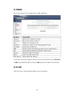
Page 22: ...t mask for the LAN port LOOPBACK IP AND SUBNETMASK IP Address Enter the IP address Subnet Mask Enter the subnet mask Enable IGMP Snooping Enable by ticking the checkbox Standard Mode In standard mode multicast traffic will flood to all bridge ports when no client subscribes to a multicast group even if IGMP snooping is enabled Blocking Mode In blocking mode the multicast data traffic will be block...

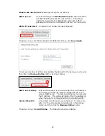
Page 23: ...ntry tick the corresponding checkbox in the Remove column and then click the Remove Entries button as shown below DHCP Server Relay Enable with checkbox and enter DHCP Server IP address This allows the Router to relay the DHCP packets to the remote DHCP server The remote DHCP server will provide the IP address This option is hidden if NAT is enabled or when the router is configured with only one B...

Page 24: ...s option NAT must be enabled in at least one PVC shown on the Advanced Setup WAN screen NAT is not an available option in Bridge mode 5 4 1 Virtual Servers Virtual Servers allow you to direct incoming traffic from the WAN side identified by Protocol and External port to the Internal server with private IP addresses on the LAN side The Internal port is required only if the external port needs to be...

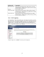
Page 25: ...e WAN interface from the drop down box Select a Service Or Custom Server User should select the service from the list Or User can enter the name of their choice Server IP Address Enter the IP address for the server External Port Start Enter the starting external port number when you select Custom Server When a service is selected the port ranges are automatically configured ...

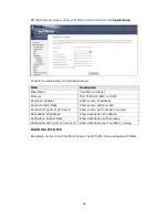
Page 26: ...when you select Custom Server When a service is selected the port ranges are automatically configured 5 4 2 Port Triggering Some applications require that specific ports in the firewall be opened for access by the remote parties Port Triggers dynamically Open Ports in the firewall when an application on the LAN initiates a TCP UDP connection to a remote party using the Triggering Ports The Router ...

Page 27: ...r port number when you select custom application When an application is selected the port ranges are automatically configured Trigger Protocol TCP TCP UDP or UDP Open Port Start Enter the starting open port number when you select custom application When an application is selected the port ranges are automatically configured Open Port End Enter the ending open port number when you select custom app...

Page 28: ...iltering This screen sets filter rules that limit IP traffic Outgoing Incoming Multiple filter rules can be set and each applies at least one limiting condition For individual IP packets to pass the filter all conditions must be fulfilled NOTE This function is not available when in bridge mode Instead MAC Filtering pg 30 performs a similar function OUTGOING IP FILTER By default all outgoing IP tra...

Page 29: ...dress Enter source IP address Source Subnet Mask Enter source subnet mask Source Port port or port port Enter source port number or range Destination IP address Enter destination IP address Destination Subnet Mask Enter destination subnet mask Destination Port port or port port Enter destination port number or range INCOMING IP FILTER By default all incoming IP traffic is blocked but IP traffic ca...

Page 30: ...29 To add a filter to allow incoming IP traffic click the Add button On the following screen enter your filter criteria and then click Apply Save Consult the table below for field descriptions ...

Page 31: ...in bridge mode Other modes use IP Filtering pg 27 to perform a similar function Each network device has a unique 48 bit MAC address This can be used to filter block or forward packets based on the originating device MAC filtering policy and rules for the WAP 5813n can be set according to the following procedure The MAC Filtering Global Policy is defined as follows FORWARDED means that all MAC laye...

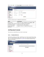
Page 32: ...ddress Defines the source MAC address Source Destination Interfaces Applies the filter to selected WAN interfaces 5 6 Parental Control This selection provides WAN access control functionality 5 6 1 Time Restriction This feature restricts access from a LAN device to an outside network through the device on selected days at certain times Make sure to activate the Internet Time server synchronization...

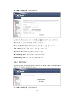
Page 33: ...the PC running the browser Other MAC Address MAC address of another LAN device Days of the Week The days the restrictions apply Start Blocking Time The time the restrictions start End Blocking Time The time the restrictions end 5 6 2 URL Filter This screen allows for the creation of a filter rule for access rights to websites based on their URL address and port number Click Add to display the foll...

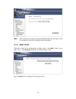
Page 34: ...o button to deny access to the websites listed Tick the Include radio button to restrict access to only those listed websites 5 7 Routing This option allows for Default Gateway Static Route and RIP configuration NOTE In bridge mode the RIP screen is hidden while the Default Gateway and Static Route configuration screens are shown but ineffective 5 7 1 Default Gateway Select a WAN Interface as the ...

Page 35: ...must be rebooted to activate the assigned default gateway 5 7 2 Static Route This option allows for the configuration of static routes Click Add to create a new static route Click Remove to delete the selected static route Click the Add button to display the following screen ...

Page 36: ... mode and select the Enabled checkbox for at least one WAN interface before clicking Save Apply 5 8 DNS 5 8 1 DNS Server To obtain DNS information from a WAN interface select the first radio button and then choose a WAN interface from the drop down box For Static DNS select the second radio button and enter the IP Address of the primary and secondary DNS server s Click Save Apply to save the new c...

Page 37: ... Dynamic DNS The Dynamic DNS service allows you to map a dynamic IP address to a static hostname in any of many domains allowing the WAP 5813n to be more easily accessed from various locations on the Internet To add a dynamic DNS service click Add The following screen will display ...

Page 38: ...ion D DNS provider Select a dynamic DNS provider from the list Hostname Enter the name of the dynamic DNS server Interface Select the interface from the list Username Enter the username of the dynamic DNS server Password Enter the password of the dynamic DNS server ...

Page 39: ...network To use this feature you must create mapping groups with appropriate LAN and WAN interfaces using the Add button The Remove button removes mapping groups returning the ungrouped interfaces to the Default group Only the default group has an IP interface To add an Interface Group click the Add button The following screen will appear It lists the available and grouped interfaces Follow the ins...

Page 40: ...ouping configuration will be 1 Default ENET1 ENET2 ENET3 and ENET4 2 Video nas_0_36 nas_0_37 and nas_0_38 The DHCP vendor ID is Video If the onboard DHCP server is running on Default and the ISP s DHCP server is running on PVC 0 36 It is for set top box use only On the LAN side the PC can get IP address from the CPE s DHCP server and access the Internet via PPPoE 0 33 If the set top box is connect...

Page 41: ...is valid 5 11 1 Local CREATE CERTIFICATE REQUEST Click Create Certificate Request to generate a certificate signing request The certificate signing request can be submitted to the vendor ISP ITSP to apply for a certificate Some information must be included in the certificate signing request Your vendor ISP ITSP will ask you to provide the information they require and to provide the information in ...

Page 42: ...organization Do not abbreviate State Province Name The state or province where your organization is located It cannot be abbreviated Country Region Name The two letter ISO abbreviation for your country IMPORT CERTIFICATE Click Import Certificate to paste the certificate content and the private key provided by your vendor ISP ITSP into the corresponding boxes shown below Enter a certificate name an...

Page 43: ...ncryption decryption Its purpose is to sign and issue certificates in order to prove that these certificates are valid Click Import Certificate to paste the certificate content of your trusted CA The CA certificate content will be provided by your vendor ISP ITSP and is used to authenticate the Auto Configuration Server ACS that the CPE will connect to Enter a certificate name and click Apply to i...

Page 44: ... options Consult the table below for descriptions of these options Option Description Enable Wireless A checkbox that enables or disables the wireless LAN interface When selected a set of basic wireless options will appear Hide Access Point Select Hide Access Point to protect the access point from detection by wireless active scans To check AP status in Windows XP open Network Connections from the...

Page 45: ...nt and in Independent BSS or ad hoc networks the BSSID is generated randomly Country A drop down menu that permits worldwide and specific national settings Local regulations limit channel range US worldwide Japan 1 14 Jordan 10 13 Israel 1 13 Max Clients The maximum number of clients that can access the router Wireless Guest Virtual Access Points This router supports multiple SSIDs called Guest SS...

Page 46: ... down box SSID stands for Service Set Identifier All stations must be configured with the correct SSID to access the WLAN If the SSID does not match that client will not be granted access Network Authentication This option specifies whether a network key is used for authentication to the wireless network If network authentication is set to Open then no authentication is provided Despite this the i...

Page 47: ...on Four network keys can be defined although only one can be used at any one time Use the Current Network Key list box to select the appropriate network key Security options include authentication and encryption services based on the wired equivalent privacy WEP algorithm WEP is a set of security services used to protect 802 11 networks from unauthorized access such as eavesdropping in this case t...

Page 48: ...ed data 6 2 1 WPS Wi Fi Protected Setup WPS is an industry standard that simplifies wireless security setup for certified network devices Every WPS certified device has both a PIN number and a push button located on the device or accessed through device software The WAP 5813n has both a WPS button on the rear panel and a virtual button accessed from the web user interface WUI Devices with the WPS ...

Page 49: ...nstructions II NETWORK AUTHENTICATION Step 3 Select Open WPA PSK WPA2 PSK or Mixed WPA2 WPA PSK network authentication mode from the Manual Setup AP section of the Wireless Security screen The example below shows WPA2 PSK mode Step 4 For the Pre Shared Key PSK modes enter a WPA Pre Shared Key You will see the following dialog box if the Key is too short or too long Step 5 Click the Save Apply butt...

Page 50: ... screen as shown in A or B below and then click the appropriate button based on the WSC AP mode selected in step 2 A For Configured mode click the Add Enrollee button B For Unconfigured mode click the Config AP button Step 7 Go to your WPS wireless client and activate the push button function A typical WPS client screenshot is shown below as an example Now go to Step 8 part IV Check Connection to ...

Page 51: ...lient For Configured mode the client must be configured as an Enrollee For Unconfigured mode the client must be configured as the Registrar This is different from the External Registrar function provided in Windows Vista The figure below provides an example of a WPS client PIN function in progress Now go to Step 8 part IV Check Connection to check the WPS connection IV CHECK CONNECTION Step 8 If t...

Page 52: ...e correct SSID to access the WLAN If the SSID does not match that user will not be granted access MAC Restrict Mode Disabled MAC filtering is disabled Allow Permits access for the specified MAC addresses Deny Rejects access for the specified MAC addresses MAC Address Lists the MAC addresses subject to the MAC Restrict Mode A maximum of 60 MAC addresses can be added Every network device has a uniqu...

Page 53: ... options Click Save Apply to implement new configuration settings Feature Description AP Mode Selecting Wireless Bridge aka Wireless Distribution System disables Access Point AP functionality while selecting Access Point enables AP functionality In Access Point mode wireless bridge functionality will still be available and wireless stations will be able to associate to the AP ...

Page 54: ... speed set the fragmentation threshold set the RTS threshold set the wakeup interval for clients in power save mode set the beacon interval for the access point set XPress mode and set whether short or long preambles are used Click Save Apply to set new advanced wireless options Field Description Band Set to 2 4 GHz for compatibility with IEEE 802 11x standards The new amendment allows IEEE 802 11...

Page 55: ...s will be fragmented and at what size On an 802 11 WLAN packets that exceed the fragmentation threshold are fragmented i e split into smaller units suitable for the circuit size Packets smaller than the specified fragmentation threshold value are not fragmented Enter a value between 256 and 2346 If you experience a high packet error rate try to slightly increase your Fragmentation Threshold The va...

Page 56: ...logy Xpress Technology is compliant with draft specifications of two planned wireless industry standards Transmit Power Set the power output by percentage as desired WMM Wi Fi Multimedia The technology maintains the priority of audio video and voice applications in a Wi Fi network It allows multimedia service get higher priority WMM No Acknowledgement Refers to the acknowledge policy used at the M...

Page 57: ...nt along with the amount of time since packets were transferred to and from each station If a station is idle for too long it is removed from this list Authorized Lists those devices with authorized access SSID Lists which SSID of the modem that the stations connect to Interface Lists which interface of the modem that the stations connect to ...

Page 58: ...ow IPoW Connection PPPoE Connection The Diagnostics menu provides feedback on the connection status of the WAP 5813n If a test displays a fail status click the Test button to retest and confirm the error If the test continues to fail click Help and follow the troubleshooting procedures provided ...

Page 59: ... 8 1 1 Backup Settings To save the current configuration to a file on your PC click Backup Settings You will be prompted for a location of the backup file This file can later be used to recover settings using the Update Settings function described below 8 1 2 Update Settings This option recovers configuration files previously saved using Backup Settings Enter the file name including folder path in...

Page 60: ...2 minutes before reopening it It may also be necessary to reconfigure your PC IP configuration to match your new settings NOTE This entry has the same effect as the Reset button The WAP 5813n board hardware and the boot loader support the reset to default If the Reset button is continuously pressed for more than 5 seconds the boot loader will erase the configuration data saved in flash memory ...

Page 61: ... Log as shown below circled in Red STEP 2 Select desired options and click Apply Save Consult the table below for detailed descriptions of each system log option Option Description Log Indicates whether the system is currently recording events The user can enable or disable event logging By default it is disabled To enable it select the Enable radio button and then click Apply Save ...

Page 62: ...level is set to Debugging all the events from the lowest Debugging level to the most critical level Emergency level will be recorded If the log level is set to Error only Error and the level above will be logged Display Level Allows the user to select the logged events and displays on the View System Log window for events of this level and above to the highest Emergency level Mode Allows you to sp...

Page 63: ...on to the ACS using the CPE WAN Management Protocol This username is used only for HTTP based authentication of the CPE ACS Password Password used to authenticate the CPE when making a connection to the ACS using the CPE WAN Management Protocol This password is used only for HTTP based authentication of the CPE WAN Interface used by TR 069 client Choose Any_WAN LAN Loopback or a configured connect...

Page 64: ...correct time zone offset and click Save Apply NOTE Internet Time must be activated to use Parental Control page 31 In addition this menu item is not displayed when in Bridge mode since the router would not be able to connect to the NTP timeserver 8 5 Access Control 8 5 1 Passwords This screen is used to configure the user account access passwords for the device Access to the WAP 5813n is controlle...

Page 65: ...field or click the Browse button to locate the image file STEP 3 Click the Update Software button once to upload and install the file NOTE The update process will take about 2 minutes to complete The device will reboot and the browser window will refresh to the default screen upon successful installation It is recommended that you compare the Software Version at the top of the Device Information s...

Page 66: ...t To save the current configuration and reboot the router click Save Reboot NOTE You may need to close the browser window and wait for 2 minutes before reopening it It may also be necessary to reset your PC IP configuration ...

Page 67: ...s allowed By setting up one or more filters specific packet types coming from the LAN can be dropped Example 1 Filter Name Out_Filter1 Protocol TCP Source IP address 192 168 1 45 Source Subnet Mask 255 255 255 0 Source Port 80 Dest IP Address NA Dest Subnet Mask NA Dest Port NA This filter will Drop all TCP packets coming from the LAN with IP Address Subnet Mask of 192 168 1 45 24 having a source ...

Page 68: ...168 1 45 24 and a destination port in the range of 6060 to 7070 All other incoming packets on this interface are DROPPED MAC LAYER FILTER These rules help in the filtering of Layer 2 traffic MAC Filtering is only effective in Bridge mode After a Bridge mode connection is created navigate to Advanced Setup Æ Security Æ MAC Filtering in the WUI Example 1 Global Policy Forwarded Protocol Type PPPoE D...

Page 69: ...es Example User Name FilterJohn Browser s MAC Address 00 25 46 78 63 21 Days of the Week Mon Wed Fri Start Blocking Time 14 00 End Blocking Time 18 00 With this rule a LAN device with MAC Address of 00 25 46 78 63 21 will have no access to the WAN on Mondays Wednesdays and Fridays from 2pm to 6pm On all other days and times this device will have access to the outside Network ...

Page 70: ...69 Appendix B Pin Assignments ETHERNET Ports RJ45 Pin Definition Pin Definition 1 Transmit data 5 NC 2 Transmit data 6 Receive data 3 Receive data 7 NC 4 NC 8 NC ...

Page 71: ...mode Turbo mode Management Compliant with TR 069 TR 098 TR 111 remote management protocols Telnet Web based management Configuration backup and restoration Software upgrade via HTTP TFTP FTP server Routing Functions PPPoE IPoA Static route RIP v1 v2 NAT PAT DMZ DHCP Server Relay Client DNS Proxy ARP IGMP Proxy Security Functions Authentication protocol PAP CHAP Port Triggering Forwarding Packet an...

Page 72: ...71 Kit Weight 1 WAP 5813n 1 RJ45 cable 1 power adapter 1 CD ROM 1 0 kg Certifications CE 0197 CE NOTE Specifications are subject to change without notice ...

Page 73: ...able SSH access for the LAN or WAN from the Management Æ Access Control Æ Services menu in the web user interface To access the router using the Linux ssh client For LAN access type ssh l root 192 168 1 1 For WAN access type ssh l support WAN IP address To access the router using the Windows putty ssh client For LAN access type putty ssh l root 192 168 1 1 For WAN access type putty ssh l support W...

Page 74: ...egistrar using the web user interface WUI on a personal computer running the Windows Vista operating system Step 1 Enable UPnP on the Advanced Setup Æ LAN screen in the WUI NOTE A PVC must exist to see this option Step 2 Open the Network folder and look for the BroadcomAP icon ...

Page 75: ...the drop down list box and set the WSC AP Mode to Unconfigured Step 4 Click the Save Apply button at the bottom of the screen The screen will go blank while the router applies the new Wireless settings When the screen returns press the Start AddER button as shown above Step 3 Step 4 ...

Page 76: ...og box will appear asking for the Device PIN number Enter the Device PIN as shown on the Wireless Æ Security screen Click Next Step 6 Windows Vista will attempt to configure the wireless security settings Step 7 If successful the security settings will match those in Windows Vista ...

Reviews: