background image


60 

A01Axxxxxx.xx | 04 

2022-11 


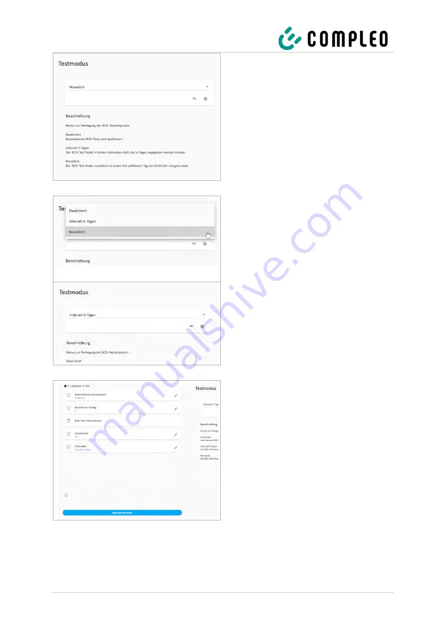
The settings for the test mode are 
displayed in the right column of the 
configuration. 

4. 

Click to open the selection field. 


The selection options are displayed. 

5. 

Select a new cycle for the test mode. 


The selected cycle is displayed. 

6. 

Confirm selection by clicking on the green 
button. 


The blue <Apply changes> button is 
displayed in the left column of the 
configuration. 

7. 

Click the <Apply changes> button and 
follow the instructions. 


Summary of Contents for A01AE11001.11

Page 1: ...Operating instructions Compleo SOLO advanced AV06 AV19 Article number A01Axxxxxx xx Issue 2022 11 Revision 04...

Page 2: ...2 3 Product description 13 3 1 Design 13 3 2 Series label 15 3 3 Technical specifications 16 4 Transport packaging and storage 20 4 1 Transport Inspection 20 4 2 Storage conditions 21 5 Installation 2...

Page 3: ...48 5 10 14Attaching the optional safety lock 49 5 10 15Safety sign 49 6 Commissioning 50 6 1 Testing the charging system 51 6 2 System start up 51 6 3 Configuration of the charging system with Comple...

Page 4: ...81 9 1 12 IsolationError L 81 9 1 13 Inoperative O 81 9 1 14 FuseError P 82 9 1 15 TemperatureSensorMissing Q 82 9 1 16 TemperatureSensorHighLimitViolation R 82 9 1 17 TemperatureSensorLowLimitViolat...

Page 5: ...LPCOverVoltageError i 91 9 1 42 LPCHighTemperatureError j 91 9 1 43 LPCSelftestError k 91 10 Maintenance 92 10 1 Maintenance plan 93 10 1 1 Automatic RCD test 93 10 2 Maintenance and repair 94 10 3 C...

Page 6: ...gn of the charging system More information about the product https www compleo cs com service installation service 1 1 Scope of application This manual is valid for the following article numbers of th...

Page 7: ...n of conformity When installing and commissioning a charging system from Compleo Charging Solutions nationally applicable standards and regulations must also be observed NOTE All standards regulations...

Page 8: ...tanding different information in this manual is presented or highlighted as follows List without fixed order List next item Subitem Subitem 1 Handling instruction step 1 2 Handling instruction step 2...

Page 9: ...rystal Display LS Charging system charging station MCB Miniature Circuit Breaker MessEG Measuring and calibration law MessEV Measuring and calibration regulations N A Not Available Applicable OCPP Ope...

Page 10: ...re presented as follows DANGER Indicates an imminent danger that will result in death or serious injury if not avoided There is great danger to life WARNING Indicates a potentially hazardous situation...

Page 11: ...ing system is used for other purposes the operator may be endangered and the charging equipment may be damaged This manual must always be accessible Note the following points If no charging process is...

Page 12: ...em from the power supply The system has life threatening DC voltages which only disappear after five minutes after switching off due to capacitor charges A corresponding period of five minutes must el...

Page 13: ...ace socket type 2 or parking position for charging plug type 2 4 Status display of the charging interfaces 5 Series label 6 Near field lighting optional 8 RFID The illustration shows a charging system...

Page 14: ...ith sliding cover AO2 Status displays and or display Display Status LED 3 colour Authentication RFID tag RFID card Giro E optional Remote authorisation optional Surge protection optional Surge arreste...

Page 15: ...8 Pictograms safety information protection class 9 QR code Serial number of the charging system 10 Metrology marking year conformity assessment body 11 Accuracy class of the measuring device accordin...

Page 16: ...ble 6 mm with and without ferrule Ethernet LSA terminals RJ45 socket Min connection cross section 26 AWG LSA terminal Max length 30 m Ripple control receiver Contacts for mains supporting load control...

Page 17: ...mber A01AE11001 11 A01AE11002 11 A01AE11003 11 A01AE11004 11 A01AE12101 11 A01AE12102 11 A01AE12103 11 A01AE12104 11 A01AE11001 22 A01AE11002 22 A01AE11003 22 A01AE11004 22 Protective devices MCB 2 C2...

Page 18: ...Data communication TCP IP Data connection LTE modem for mini SIM card frequency transmission power 800 MHz 900 MHz 1800 MHz 2100 MHz 2600 MHz 23 0 1 dBm Backend communication OCPP 1 6J 2 0 ready RFID...

Page 19: ...3 according to IEC 60898 1 IEC 60947 2 or IEC 61009 1 deviations possible due to country specific regulations 4 Residual current circuit breaker must be upstream of the charging system 5 Surge protect...

Page 20: ...charging system with that of the delivery documents to exclude faulty deliveries 3 Check delivery according to purchase and scope of delivery for completeness 4 Proceed as follows in case of deviatio...

Page 21: ...ransported in If this is not possible for undetermined reasons it should be stored in the installation position of the charging system Ambient temperature for storage 25 C to 50 C Permissible relative...

Page 22: ...se damage to the unit Do not leave the charging station unattended with the installation cover open 5 2 Notes on mechanical installation WARNING Incorrect installation and start up Improper performanc...

Page 23: ...sufficient load bearing capacity the fastening may tear out and cause the charging system to fall down Damage to the charging system can be the result Ensure that the wall construction has sufficient...

Page 24: ...ons during electrical installation In Germany these include the following safety requirements DIN VDE 0100 100 DGUV Regulation 1 DGUV Regulation 3 4 TRBS 1201 NOTE The protection technology required f...

Page 25: ...install an additional RCCB in the upstream sub distribution The additional RCCB must be selective to the RCCB installed in the charging system or The self test of the internal RCCB must be deactivated...

Page 26: ...ox and the bottom shell 4 Lift the connection box 1 at the bottom unlatch and remove it 5 Turn the charging system onto its rear and put it down Fig 3 SOLO rear side 6 Loosen and remove 2 TORX screws...

Page 27: ...ooding is to be expected Areas where heat domes or heat accumulation can occur The substrate must have sufficient strength and load bearing capacity to withstand the mechanical loads Provide sufficien...

Page 28: ...SMC base 8 Feed the supply lines through the centre of the base 9 Fix the base by filling 10 Feed the supply line through the pillar 11 Place the pillar on the base and screw it down 12 Fasten the ch...

Page 29: ...s through the soil to the excavation pit and lead them through the side recess in sufficient length approx 1800 mm centrally in the base upwards out of the pit 5 Align the height of the SMC base in th...

Page 30: ...pe 2 to the upper opening 3 Pull the supply lines out of the upper opening as far as necessary 4 Erect the pillar and place it on the prepared SMC base While doing so carefully pull the supply lines f...

Page 31: ...round 6 Insert ground anchorage 7 Feed the supply line through the pillar 8 Place the pillar on the ground anchoring and screw it down 9 Fasten the charging system with installation material 10 Prepar...

Page 32: ...600 mm free space around the charging system for heat dissipation Laid supply line Installation material and tools Depending on ground conditions 4 suitable ground anchors e g expansion or injection...

Page 33: ...e on the ground 7 Move the pillar to the side so that the markings on the ground are accessible Check that the supply lines are not twisted or strained 8 Drill holes on the markings using a suitable d...

Page 34: ...anchors While doing so carefully pull the supply lines further out of the upper opening to avoid looping 2 Align the pillar so that the fixing holes are aligned with the mounting points of the ground...

Page 35: ...bolts of the pillar 2 Place the large diameter washers on the threaded bolts 3 Screw nuts onto the threaded bolts and hand tighten 4 Check the terminal box for correct seating and tighten the nuts in...

Page 36: ...desired side of the pillar at the existing mounting holes of the mounting plate and fix with the fixing screws of the pillar 2 On the back of the mounting plate screw the nuts onto the fixing screws a...

Page 37: ...st 600 mm lateral free space around the charging system for heat dissipation At least 150 mm distance to the building ceiling At least 900 mm from the top of the ground or the soil 1 Connection box 2...

Page 38: ...onnection box on the wall at the selected position and align it using the integrated spirit level 2 Mark the boreholes 1 5 3 Drill boreholes with a depth of 8 mm and 60 mm 4 Insert 8 mm hole plug 5 Mo...

Page 39: ...om above also break out and deburr the upper pre punched tab 3 3 Guide the supply line of the required length through the grommet in the connection box and secure it with the supplied screws 4 x 25 mm...

Page 40: ...6 mm with and without ferrule 7 Connect all conductors of the supply line to the external wiring side according to the figure opposite 8 Ensure that the individual wires are connected correctly and t...

Page 41: ...uipped with a surge protection device type 1 2 3 DIN EN 61643 11 and whose use is prescribed by local directives See chapter 3 3 Technical specifications page 16 NOTE The equipotential bonding conduct...

Page 42: ...f devices M 1 5 Nm Cable routing from above Select the cable length up to the lower edge of the terminal box Cable routing from below Select the cable length up to the upper edge of the connection box...

Page 43: ...eated 3 Preliminarily secure the bottom shell against falling down using the screws supplied raised head 4 x 12 mm in mounting holes 2 and 3 4 Unclip the lower lighting strip 6 on the left hand side s...

Page 44: ...ng the internal supply line 1 Insert the bundled connector of the permanently installed connection line into the terminal block of the power supply line in the terminal box and snap it into place Fig...

Page 45: ...2 Strip the wires 18 mm 3 Connect the line on the external wiring side and ensure that the terminal screws are tightened M 2 0 4 0 Nm Fig 23 Equipotential bonding terminal NOTE This chapter only appl...

Page 46: ...hannel provided and fix it in place with the cable ties supplied 2 Crimp the RJ45 plug onto the data line or use a prefabricated network cable and connect it to the RJ socket 2 Connection via LSA term...

Page 47: ...Connect the ripple control line to the terminal 1 Fig 25 Radio connection Functions with terminal assignment GND 1 Input 1 0 charging power 2 Input 2 30 charging power 3 Input 3 60 charging power 4 In...

Page 48: ...ck option 1 Housing cover 2 Retaining screw with countersunk head 1 Place the housing cover on the upper retaining bar of the bottom shell and close it downwards Check for correct and tight fit 2 Ligh...

Page 49: ...s flush with the cylinder 3 Press the housing cover lightly at the bottom and insert the lock 4 Turn the key anticlockwise to the horizontal position and remove Unlocking 1 Insert the key turn it cloc...

Page 50: ...lations during commissioning The correct mechanical installation is checked according to the following criteria The degree of protection of the housing is not reduced or removed The charging system ha...

Page 51: ...e charging system has been correctly installed the system can be started 1 Switch on the power supply 2 Switch on the line and residual current circuit breaker The system starts up The duration of the...

Page 52: ...m is established After logging in an overview of the parameters that can be called up or changed is listed To connect to the charging system the end device used must have an IP address in the same IP...

Page 53: ...IPv4 5 Enter the IP address from the range 192 168 1 xxx Note The IP 192 168 1 100 is assigned for the charging station and must not be used for the configuration of the end device or the computer The...

Page 54: ...68 1 100 The DUCTO start page is displayed 6 3 3 Operator login The start page shows information about the charging status of the charging interfaces After logging in as an operator the user can set v...

Page 55: ...2 Click the Password button and follow the instructions ATTENTION The password cannot be reset to the initial password after the password has been changed The current password must therefore be kept...

Page 56: ...ayed 3 Click the Off button The button is highlighted in red 4 Confirm selection by clicking on the green button The blue Apply changes button is displayed in the left column of the configuration 5 Cl...

Page 57: ...restart The changes are adopted 6 3 5 Log in as electrician If the Log in as electrician checkbox is ticked when entering the password the instructed electrician can make advanced settings for configu...

Page 58: ...ructions See also Example Changing the RCD test cycle Optional Changing the password 8 Click the Password button and follow the instructions ATTENTION The password cannot be reset to the initial passw...

Page 59: ...59 1 Click the Charging station button The settings for the parameters of the charging station are displayed 2 Click the RCD button The settings for the RCD residual current device are displayed 3 Cl...

Page 60: ...pen the selection field The selection options are displayed 5 Select a new cycle for the test mode The selected cycle is displayed 6 Confirm selection by clicking on the green button The blue Apply ch...

Page 61: ...n the left column of the configuration 8 Click the Apply changes button and follow the instructions 9 Perform a restart The changes are adopted 6 4 DUCTO Guide More information about DUCTO https www c...

Page 62: ...ompleted and a charging cable has been connected to the charging system and or the vehicle Giro e With the Giro e method a charging process is started on a charging system by means of a Giro card and...

Page 63: ...by brief instructions on how to start and end a charging process The brief instructions are divided into variants and differ depending on the type of charger interface and operating method DANGER Dang...

Page 64: ...app for smartphone or tablet or start web interface 2 Follow the instructions of the app or web interface for the authorisation process LED lights up green when authorisation is successful 3 Follow th...

Page 65: ...ng plug into the vehicle s socket 3 The display indicates charging process preparation Vehicle connected Preparing for charging 4 The display indicates the charging process Charging started In the eve...

Page 66: ...ions of the app or web interface for finishing the charging process 7 3 2 Ending charging with type 2 socket 1 The display indicates the end of the charging process Type 2 Charged XXX Charging duratio...

Page 67: ...ug into charging station to end charging duration 3 Pull the charging plug out of the vehicle s socket 4 The display indicates the removal of the plug Type 2 Insert plug into charging station to end c...

Page 68: ...to output states processes or errors via a display and or LEDs Depending on the type configuration and the number of charger interfaces of the charging system the type of representations on the displ...

Page 69: ...completed The charging process can be performed 5 The charging system indicates the Please connect vehicle state The plug of the corresponding charger interface should be connected to the vehicle 6 Th...

Page 70: ...e charging process at the corresponding charger interface is in progress The charged capacity is displayed The charging duration is displayed Have a good trip 14 The charging system indicates the Disc...

Page 71: ...d Authorisation using a RFID card or chips is required alternatively key 3 can be used 23 The charging system indicates the 1 Scroll OK Cancel state The displayed menu can be operated using the icons...

Page 72: ...ning state The charging process can be stopped at the corresponding charger interface using key 3 The charged capacity is displayed The charging duration is displayed An isolation warning is displayed...

Page 73: ...corresponding charger interface should be unplugged from the charging system and plugged in again 39 The charging system indicates the Preparing charging process Stage state The charging process is i...

Page 74: ...74 A01Axxxxxx xx 04 2022 11 45 The charging system indicates the Error during data transfer state An error has occurred during the data transfer of the charging process...

Page 75: ...ED green grey 5 The charging system indicates an unsuccessful authorisation LED green blue 6 The charging system indicates the start of a charging process LED blue grey 7 The charging system indicates...

Page 76: ...odes in the event of a fault 8 2 Residual current circuit breaker RCCB In the event of a residual current the residual current circuit breaker trips and the charging system is switched off To switch o...

Page 77: ...ion software must be called up for error detection see chapter 6 3 Configuration of the charging system with Compleo DUCTO page 52 The DUCTO start page displays the status of the charging system and p...

Page 78: ...1 3 HighTemperature C Name HighTemperature Area Station Description OCPP1 6 Temperature inside Charge Point is too high Temperature inside Charge Point is too high Reported by Station Handling The err...

Page 79: ...1 6 PowerMeterFailure F Name PowerMeterFailure Area Connector AC Description OCPP1 6 Failure to read electrical energy power meter Reported by Connector Handling The error is shown on the display Ind...

Page 80: ...ltage has dropped below an acceptable level Reported by Connector Handling The connector terminates the charging process The error is shown on the display Indication on display I Action Have the power...

Page 81: ...rs with isolation problems before and during a charging process Reported by Connector Handling The error is shown on the display Indication on display L Action No action possible by operator Notify cu...

Page 82: ...temperature sensors provide a value Reported by Connector Handling The error is shown on the display The maximum charging current is lowered Indication on display Q Action No action possible by operat...

Page 83: ...em Notify customer service if the error persists 9 1 18 AutomaticRcdTestRunning T Name AutomaticRcdTestRunning Area Station Description An automatic RCD switch test is carried out Reported by Station...

Page 84: ...in the control unit and the PSU board in the power unit Reported by Station Handling The error is shown on the display Ongoing DC charging processes are terminated Indication on display X Action Switc...

Page 85: ...valid insulation status has occurred during a DC charging process Reported by Connector Handling The charging process is aborted The error is shown on the display Indication on display 1 Action Switch...

Page 86: ...nector Description The error occurs when the SAM has no more free memory for new charging processes Reported by SAMConnector Handling The charging process is aborted The error is shown on the display...

Page 87: ...n SAM and the touch keys for SAM query is disturbed Reported by SAMAdapter Handling The charging process is aborted The error is shown on the display No new charging process possible Indication on dis...

Page 88: ...ug could not be unlocked Reported by Connector Handling New charging processes cannot be started The error is shown on the display Indication on display a Action Eliminate possible tensile stress on t...

Page 89: ...or Area Connector Description An unauthorised charging cable has been detected 13 A cable or undefined cable Reported by Connector Handling Charging cannot be started with this cable The error is show...

Page 90: ...es cannot be started The error is shown on the display Indication on display g Action No action possible by operator Notify customer service 9 1 40 ShortCircuitError h Name ShortCircuitError Area Conn...

Page 91: ...too high Reported by Connector Handling New charging processes cannot be started The error is shown on the display Indication on display j Action Check the location of the charging system for direct s...

Page 92: ...cyclically recurring inspection according to the maintenance plan In special cases the cycles can be shorter DANGER Danger due to electric current Touching live parts will result in electric shock wi...

Page 93: ...foils covers Check for function e g sliding cover parking position Charging system Check for function e g start and stop of a charging process at all charger interfaces As required Charging system Cle...

Page 94: ...stem when it is undamaged In the event of damage immediately disconnect the charging system from the power supply at the circuit breaker and take suitable safety measures to prevent it from being swit...

Page 95: ...pplied foiling or paintwork should be used as cleaning agents for the external housing If chemical agents are used during cleaning the work must be carried out outdoors or if this is not possible only...

Page 96: ...y installed safety elements such as MCB RCD and any installed main switch Release the upstream fuse element of the charging system Dismantling may only be carried out after it has been established tha...

Page 97: ...at the end of its service life To return the product contact the manufacturer or dealer The separate collection of Waste from Electrical and Electronic Equipment WEEE is intended to enable the reuse...

Page 98: ...on 24 Electrical voltage 12 Ending the charging process 66 Equipotential bonding 41 Error display 77 EU Declaration of Conformity 105 G Ground mounting 31 H Handling 12 Housing dimensions 100 I Instal...

Page 99: ...ons 11 Safety sign 49 Scope of application 6 Series label 15 Signals 75 SIM 47 Storage 20 Storage conditions 21 System start up 51 T Technical specifications 16 Test 51 Transport 20 Transport Inspecti...

Page 100: ...Annexes 100 A01Axxxxxx xx 04 2022 11 13 Annexes 13 1 Housing dimensions...

Page 101: ...Annexes 2022 11 A01Axxxxxx xx 04 101 13 2 Commissioning and test report for AC charging systems Test report for AC charging systems from Compleo Charging Solutions AG...

Page 102: ...Annexes 102 A01Axxxxxx xx 04 2022 11 Test report for AC charging systems from Compleo Charging Solutions AG...

Page 103: ...Annexes 2022 11 A01Axxxxxx xx 04 103 Test report for AC charging systems from Compleo Charging Solutions AG...

Page 104: ...Annexes 104 A01Axxxxxx xx 04 2022 11 Test report for AC charging systems from Compleo Charging Solutions AG...

Page 105: ...Annexes 2022 11 A01Axxxxxx xx 04 105 13 3 EU Declaration of Conformity...

Page 106: ...Annexes 106 A01Axxxxxx xx 04 2022 11...

Page 107: ...Annexes 2022 11 A01Axxxxxx xx 04 107...

Page 108: ...Annexes 108 A01Axxxxxx xx 04 2022 11...

Page 109: ...Annexes 2022 11 A01Axxxxxx xx 04 109...

Page 110: ...Annexes 110 A01Axxxxxx xx 04 2022 11...

Page 111: ...Annexes 2022 11 A01Axxxxxx xx 04 111 Notes...

Page 112: ...n part without written permission All illustrations in this document serve as examples only and may differ from the delivered product All information in this document is subject to change without noti...

Page 113: ...Annexes 2022 11 A01Axxxxxx xx 04 113...

Page 114: ...Annexes 114 A01Axxxxxx xx 04 2022 11...

Reviews: