


Installing the SAN Integrated Switch
2–11
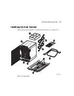
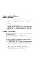
Figure 2–5: Align holes in Upper Rear Bracket with the four screw holes on the SAN Integrated Switch
d. Attach the straight section of the right bracket to the SAN Integrated Switch with
four 8-32 X 5/16 inch Phillips countersunk screws. The flat side of the bracket
should lay against the SAN Integrated Switch.
e. Repeat steps c and d for the straight section of the left Upper Rear Bracket.
4. Insert four cage nuts in the rails. They are used to attach the Front Rail Brackets of the
SAN Integrated Switch to the rails in the rack (see Figure 2–6):
a. On the left front rail, count up three square openings from the upper screw of the
Rack Mount Bracket. Insert the first cage nut.
b. Measure 26 square openings above first cage nut, and insert second cage nut.
c. Repeat steps a and b for the right front rail, inserting third and fourth cage nuts.
SHR-2201A