


2–10
SAN Switch Integrated/32 and Integrated/64 Installation and Hardware Guide
2–10
SAN Switch Integrated/32 and Integrated/64 Installation and Hardware Guide
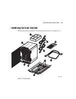
2. Attach the Rack Mount Brackets (item 3) to the rack rails (item 2) to create a shelf:
a. Loosen the screws which connect the two parts of each Rack Mount Bracket.
b. Adjust the depth of the bracket to fit into the rack. Leave the length-adjustment
screws loose until after you have attached the Rack Mount Brackets.
c. Install each Rack Mount Bracket with the notched end aligned with the front
(cable-side) of the SAN Integrated Switch, in such a way that cooling air of all
components in the rack is flowing the same direction (item 1).
d. Attach the left and right Rack Mount Brackets to the rails in the rack. Use two
1/4-20 X .5 inch Phillips head screws to attach the front of each bracket. Use four
1/4-20 X .5 inch Phillips head screws to attach the rear of each bracket.
e. Tighten the length-adjustment screws in each Rack Mount Bracket.
f. Tighten the 1/4-20 Rack Mount screws.
3. Attach the Upper Rear Brackets:
a. Disassemble each two-part Upper Rear Bracket.
b. Set aside the L sections (item 5). Attach these after you install the SAN Integrated
Switch in the rack.
c. Align the straight section (item 4) of the right bracket with the four screw holes in
the right side of the SAN Integrated Switch, as shown in Figure 2–5.