TECP-90-814 • Rev C • October 2020
Page 37
© 2020
CommScope
. All Rights Reserved.
e. When the microcables with non-functional connectors have been spliced, proceed to step 9.
7. Do the following for each microcable terminated with 12-connector fanout assemblies:
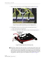
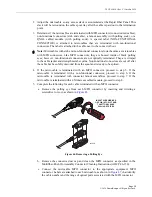
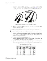
a. If the fanout is wrapped within a pulling sock, such as shown in
pulling sock from the end of the microcable by first peeling away the tape and then
cutting the two cable ties at the point shown. Next, slide the sock off the cable
assembly and remove the pink bag from the connectors. If a pipe protection is also
present (used for fanout assemblies with 900 micron fibers only), remove the pipe
(refer to
).
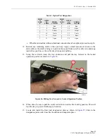
b. Before connecting an individual connector to the ODF or fiber panel, remove the
ferrule dust cap from the connector and clean the connector as specified in the Optical
Fiber Connector Wet and Dry Cleaning Instructions (ADCP-90-159).
Figure 48. Removing Pulling Sock from Fanout Assemblies
1
8
Black
2
20
Black
1
9
Yellow
2
21
Yellow
1
10
Violet
2
22
Violet
1
11
Rose
2
23
Rose
1
12
Aqua
2
24
Aqua
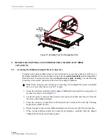
Note:
For cables equipped with 12-connector fanout assemblies, kits are available for
securing the fanouts to an Optical Distribution Frame including NGF, NG3, LSX, FCM,
and NG4access. A universal kit is also available for attaching 9 foot long 2 mm fanout
assemblies to a Glide or interbay management panel.
Table 2. Optical Port Designation
MICR
O
CABL
E
OPTIC
AL
PORT
FIBER
COLOR
MICR
O
CABL
E
OPTIC
AL
PORT
FIBER
COLOR


