TECP-90-814 • Rev C • October 2020
Page 22
© 2020
CommScope
. All Rights Reserved.
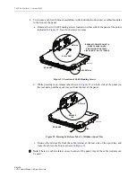
g. Re-install the two #4-40 bonding screws (removed in step 8a) on either side of the
); tighten to 6 inch-lbs (0.7 Nm) of torque.
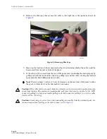
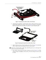
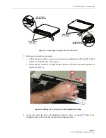
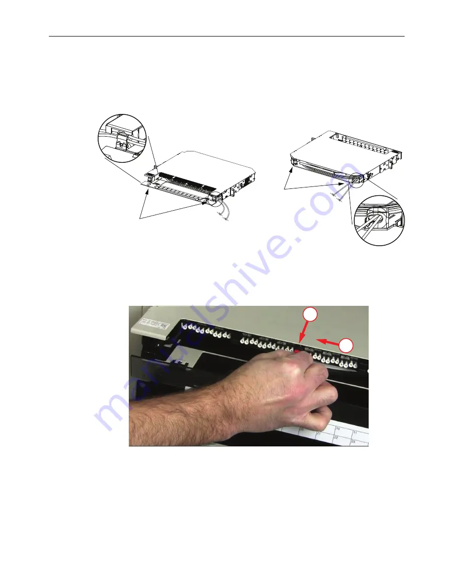
9. After unwinding the microcable, ensure that the microcable is still within the cable
retainer at the point where the microcable exits the panel as shown in
Figure 25. Placing Microcables Within Cable Retainer
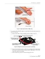
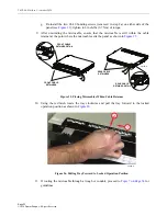
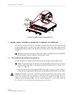
10. Using the red latch, rotate the tray clockwise and pull the tray forward to the locked
operation position as shown in
.
Figure 26. Pulling Tray Forward to Locked Operation Position
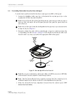
11. If routing the microcable through a trough or conduit, proceed to
guidelines.
26155-A
REAR CABLE
RETAINERS
FRONT CABLE
RETAINERS
FRONT CABLE
RETAINER DETAIL
REAR CABLE
RETAINER DETAIL
25910-A
1
2

