TECP-90-814 • Rev C • October 2020
Page 20
© 2020
CommScope
. All Rights Reserved.
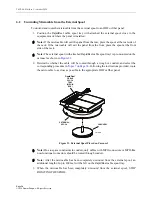
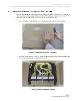
8. To re-route a cable with fanout assemblies (with individual connectors) or cabled modules
to the front of the panel:
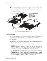
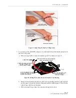
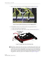
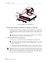
a. Remove the two #4-40 bonding screws located on either side of the panel at the points
. Save both screws for reuse.
Figure 21. Location of #4-40 Bonding Screws
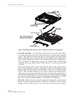
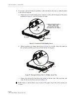
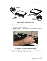
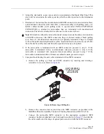
b. While pressing in on release tabs (shown in
) on both side of the panel (on
the rear side), pull the spool tray out from the rear of the panel.
Figure 22. Pressing In Release Tabs To Withdraw Spool Tray
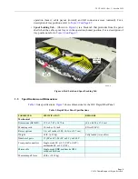
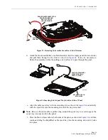
c. Remove the microcable from the cable retainer at the rear side of the spool tray and
route the cable to the front as shown in
.
Note:
There is a cable retainer on each corner of the panel. Any of the cable retainers can
be used.
26151-A
SEE DETAIL A
*REMOVE SCREWS FROM BOTH
SIDES OF PANEL WHEN
REINSTALLING TIGHTEN TO
6 INCH-LBS (0.7 Nm) OF TORQUE.
REAR SIDE
*4-40 SCREW
DETAIL A
26153-A
REAR SIDE
DETAIL A
RELEASE
TAB

