background image

Page 13 

Copyright © 2005  -  ASR Electronics. All rights reserved. 


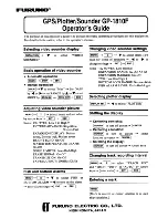
A blob of fresh hot-melt glue can now be applied to 
the tops of the standoffs and the buffer board set in 
place. The connector pins have also been partially 
inserted in the photo.  
 
At this point if you’re not installing the Aux Input 
switching board as well, skip over the next section 
and proceed to the following one. 


Auxiliary Input PCB: 

 
There are two different connection schemes, depending on whether the input board is installed on its own, 
or in conjunction with the output buffer board. The power switching is performed by the output buffer, 
therefore in these installations the input derives switched 12V from the buffer board. If stand-alone, the 
input board has a small additional “daughterboard” to perform the power switching. Look at the photos 
below for a view of the completed installation in each case.  


Again, pairs of colour coded wires are supplied for the signal connections – red/orange for the right channel, 
and white/grey for the left. (at this point there is no front/rear, the fader function is applied further on in the 
signal chain) 

 
 The capacitors C1528 and C1529 must be 
removed from the base unit board and these wires 
soldered in their place. (refer to the photo – 
differences exist between standard and premium, 
but they’re very close in this section) The leads of 
the capacitors have been bent over slightly during 
manufacture, and this makes them a little difficult 
to remove – begin by working from the bottom of 
the PCB, and using a small flat tip jeweller’s 
screwdriver in conjunction with the iron melt the 
solder on each joint and use the screwdriver tip to 

Summary of Contents for VY-VZ

Page 1: ...out cable assembly terminated with gold RCA sockets and a bullet connector a guide template to assist with the positioning of the slot which is to be cut into the cradle metalwork some various intern...

Page 2: ...cradle metalwork following the cutting of the slot A larger file can be used provided adequate care is taken an ice cream stick with emery paper is a good substitute A Dremel style rotary tool It doe...

Page 3: ...tches the wires just tend to pull out of the unit rather than pulling the unit out of the cradle The clips in the head unit which are pushed aside by these wires have a small tang pressed into them an...

Page 4: ...would say even brutal but it will come out If the wires tend to be pulling out of the unit grab the file and spend five minutes on filing the notches in the wires My wires work every time in a few se...

Page 5: ...et lock must be disengaged before completely separating the two halves of the main unit The procedure for this will be outlined shortly Along each side of the main assembly there are two T 10 screws f...

Page 6: ...e and preferably give the surface a wipe with some solvent such as acetone or lacquer thinner Don t go crazy with the solvent though you might start dissolving the connector body Just a slightly moist...

Page 7: ...iminary work can take place and the adhesive allowed to cure without too much impact on the total job time Now we can get back to the car and begin removing the necessary trim panels and extract the c...

Page 8: ...edge with your fingers use a stubby flat blade screwdriver or similar Be careful not to scratch or mar the plastic panel Once the clips at the front are released then pull back to release the clips at...

Page 9: ...be straightened easily anyway Again this is another of those situations where you mustn t pull too far because you need to release the tabs which retain the connector sockets Once you have the cradle...

Page 10: ...le You need to slide the passenger seat all the way back and it s still hard to get to With these screws removed the lower panel should now lift away At this point grab a cup of tea or coffee and have...

Page 11: ...move it In really stubborn cases where the via won t clean out use a pointed toothpick heat until the solder melts and poke the toothpick through from the other side Once the solder solidifies again p...

Page 12: ...for me but feel free to use whichever you like It is recommended though is to route the signals the way I have ie channel numbering 1 to 4 In this way the colour coding scheme I have used helps preven...

Page 13: ...oard has a small additional daughterboard to perform the power switching Look at the photos below for a view of the completed installation in each case Again pairs of colour coded wires are supplied f...

Page 14: ...the standoffs to the base unit PCB in readiness to mount the input board Don t mount it yet though you need to solder the connections Cut the wires to length allowing a little slack strip about 4mm o...

Page 15: ...quare panel behind the window switches In this case a template has been included with the kit to use as a guide for drilling the holes Another much more invisible location is the small corrugated pane...

Page 16: ...hen pushing the pin into the receptacle avoid using a sharp metal tool such as a jeweller s screwdriver as this can weaken the wire at the connection point and it may break I use a wooden toothpick it...

Page 17: ...to the connector When it s seated correctly slide the lock tabs to the locked position and make sure both ends of the locking tab are in place Replace the side screws and return the bottom cover plate...

Page 18: ...the output cables through the back and run them behind the existing harness connectors As you begin sliding the cradle in gently pull the lead out cables from behind below so that they don t fold back...

Reviews: