Reflect-O-Ray
®
EDS 6
Installation, Operation & Service
Combustion Research Corporation
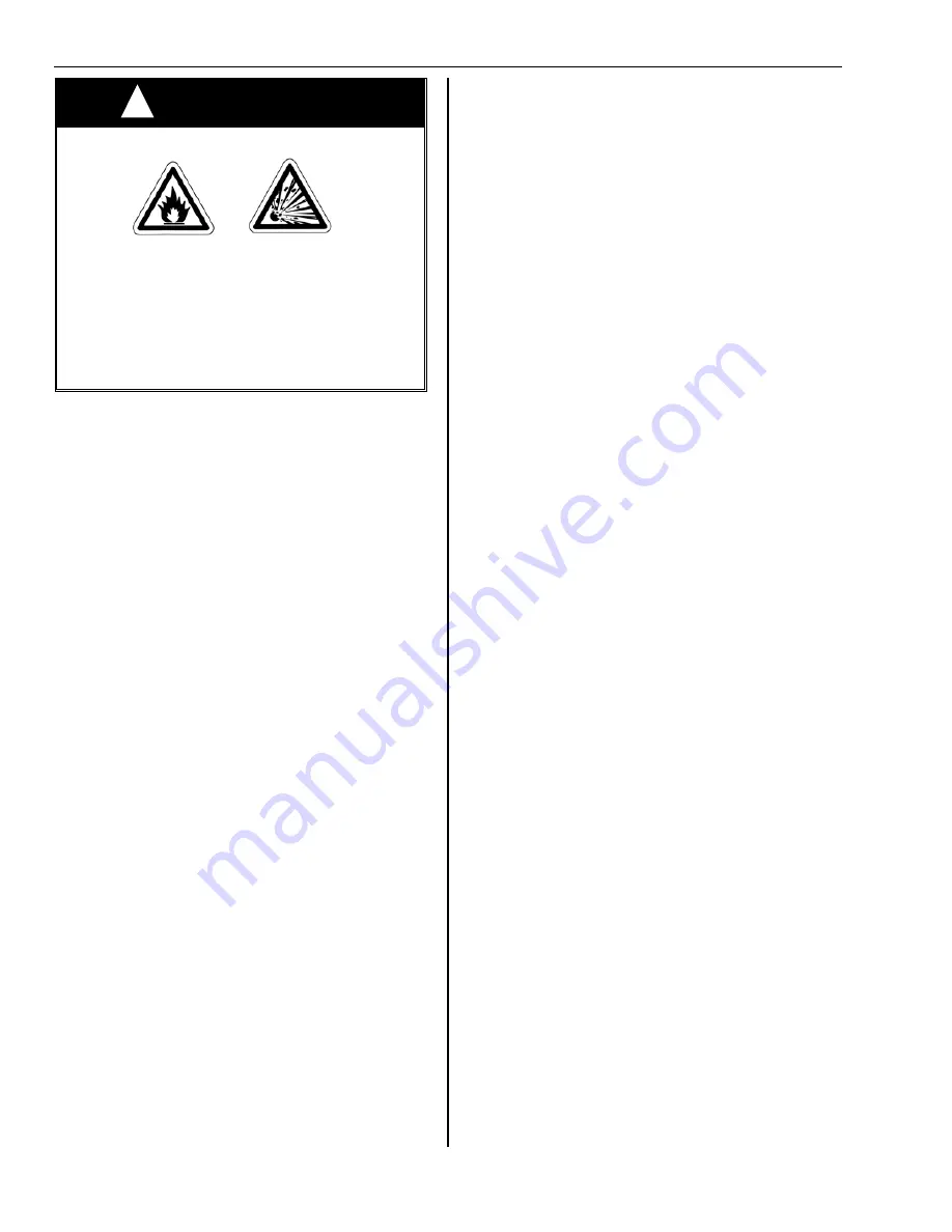
WARNING
FIRE OR EXPLOSION HAZARD
IMPROPER INSTALLATION, ADJUSTMENT,
ALTERATION, SERVICE OR MAINTENANCE
CAN CAUSE DEATH, SEVERE INJURY
AND/OR PROPERTY DAMAGE.
It is the installer's final responsibility to verify correct
gas usage.
Do not use a gas control set for natural gas on LP Gas
or a gas control set for LP Gas on Natural Gas.
4. Natural Gas Service
a. Meter and pipe work to be adequate size for total
building requirements.
b. 1015 BTU/ft3 at minimum of 7" W.C. at input side of
burner regulator during full operational load.
(Manifold pressure is 3.5" W.C.).
5. Propane Service
a. Storage tanks are large enough to vaporize
required maximum load and fitted with heating
equipment as required by application.
b. Vaporizer system and high press regulators system
installed as required and set at 13.5 W.C..
c. 2500 BTU/ft3 at minimum of 11.0" at input side of
regulator on Reflect-O-Ray burner during operation.
(Manifold pressure is 10.0" W.C..)
6. All gas valves in meter house and service cocks' open.
All feed lines have been purged of air used at time of
pipe work leakage test.
7. Exhauster has been checked for fan rotation, clockwise
viewed from motor end.
8. Flex connection to fan inlet secure and free of leaks.
9. Blast damper pinned, secured, and set so that the
vacuum cannot be altered.
Notes
1. Before attempting to recycle unit after a nuisance shut
down: On flame failure or expiration of trial ignition,
electrical supply power to burner must be interrupted
for 5 minutes to allow safety switch to reset. Power
can be interrupted at burner service switch or at the
thermostat.
2. Do not attempt to field repair control components. It is
recommended defective components be replaced as
factory replacement units.
A. PRELIMINARY REQUIREMENTS PRIOR TO
STARTING SYSTEM
1. The system must be installed in compliance with
clearances to combustibles (see page 6 & 7). Units
installed in public garages should be in accordance
with the ANSI/NFPA 88A-(current standard) for USA
and CAN/CGA 1-B149.1 and .2 for Canada. Units
installed in aircraft hangars should be in accordance
with ANSI/NFPA 409-(current standard) for USA and
CAN/CGA 1-B149.1 and .2 or enforcing authority for
Canada. All reflectors should be in position and
installed according to the installation instructions and
Start Up section tube system of this manual.
2. Make sure gas pipes have been purged of air that
might be in the pipe work. It must be adequately sized
so that a minimum of 7" W.C. and maximum of 10"
W.C. pressure at the burner can be obtained for
natural gas and 11 " W.C. minimum, 13.5" W.C.
maximum pressure for propane. The gas pipe work
should also have been tested with soap and water at
all joints as specified by local codes. It should be
noted that all service cocks on individual burner should
be closed prior to testing to avoid damage to the gas
regulator at each burner.
3. The electrical system must be installed according to
local codes and the wire must be adequately sized for
the installation in accordance with the Electrical Wiring
Specification in the Installation Instructions and Start-
Up section of this manual. See that the fan is correctly
wired so the exhauster is running in the correct
direction and that none of the equipment is pulling
more than the specified capacities stated in the
Electrical Wiring section mentioned above.
4. The vacuum of each burner must be set by manually
adjusting the damper. This is required for proper
operation and performance.
B. TO START SYSTEM
1. Check to insure that main gas cock from meter is
open.
2. Check all burners to insure that gas cocks at each
burner are open.
3. Turn the main power switch ON and check fuse.
4. Set the thermostat higher than the existing
temperature of the area to be heated. The following
steps should then take place automatically:
a. The vacuum exhauster is powered and will start.
The vacuum created by the exhauster closes the air
flow switch and supplies power to the burner,
opening the gas solenoid and allowing gas into the
burner chamber. The spark igniter will ignite to gas.
b. All three indicator lights in the burner should be on,
proving the contact of the main gas valve unit, the
airflow switch, and electrical power monitor (See
page 35 for description and function of indicator
lights).
5. Check all burners to see that they are operating.
Flame should be visible through the view window and
all three burner indicator lights on.
6. Set the thermostat down to the desired temperature.
7. When the system is initially fired, any oil that is on the
radiant tube and fittings will burn off and form a light
haze in the building which can best be removed by
ventilation system in the building, or opening doors.
This is a one-time event and will not recur.
8. On start-up there will be condensation in system for
approximately 2 minutes as fan discharge temperature
gets above the condensation point. The condensation
will be dried up in the pipe and discharged through the
fan. This results in a slight spitting of this moisture out
of the fan discharge for approximately 4 minutes from
initial start-up.
!
Page 34


