Comau e.DO Safety Requirements, Technical Features And Assembly And Integration Instructions Download Page 8

Comau Robotics Product Instruction

8

SAFETY REQUIREMENTS FOR E.DO GRIPPER USE

1.3 During the use

Minimum safety requirements to be followed during the Robot use are given below:

the e.DO Gripper can be used by children (age > 14 years old) and by persons with 
reduced physical, sensory or mental capabilities, or with insufficient experience 
and knowledge, provided that they are under the supervision of an adequately 
trained and informed adult, responsible for the safe use of the Robot itself. Children 
must not play with the equipment, they must not perform cleaning and routine 
maintenance operations.

during motion, do not insert body parts (fingers, hands, arms, etc.) between the 
gripper fingers or gears of the e.DO Gripper in order to avoid possible pinching;

handle exclusively objects of conformation such as to guarantee a good grip on the 
part of e.DO Gripper;

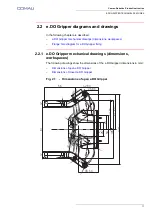
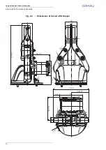
during the use, provide a sufficiently large free space around the Robot equipped 
with the e.DO Gripper (greater than the operating range of the Robot with e.DO 
Gripper, see 

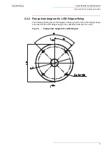
par. 2.2 e.DO Gripper diagrams and drawings on page 11

 and 

Fig. 1.7 - Robot workspace in 6 axes configuration on page 16

 and 

Fig. 1.8 - Robot 

workspace in 4 axes configuration on page 17

 on the “

Robot e.DO

 - 

Safety 

requirements and technical specifications

” handbook) in order to avoid any Robot 

impacts that could cause pinching or crushing;

do not suspend or fix objects (or similar) to the Robot structure or to the e.DO 
Gripper during the operation;

in case of 

Integration of perimeter protective guards for the use of the e.DO Gripper 

for handling purpose

, periodically check the correct functioning of the guard 

interlocking devices, connected to the “Fence” input and of an additional 
emergency button connected to the “E-Stop” input on the apposite J8 connector on 
Robot base; activate the devices and verify the stop of the Robot.

Do not use the e.DO Gripper working with wet or damp hands or feet.

In the event of fault or malfunctions, do not independently carry out dismantling or repair 
attempts on the Robot or on the e.DO Gripper; contact the Comau Service Centre, as 
indicated in the “

Robot e.DO

 - 

Certifications, Service, Warranty

” supplied with the Robot 

itself. See also the following address: edo.cloud/support-and-contacts/.

Summary of Contents for e.DO

Page 1: ...per Safety requirements technical features and assembly and integration instructions Requirements technical features and instructions for safe installation and use of the e DO Gripper CR00758190 en_00...

Page 2: ...p A Any reproduction even partial is prohibited without prior written authorization from COMAU S p A COMAU reserves the right to modify without notice the features of the product presented in this ha...

Page 3: ...eneral technical features 10 e DO Gripper diagrams and drawings 11 e DO Gripper mechanical drawings dimensions workspaces 11 Flange hole diagram for e DO Gripper fixing 13 Electrical diagram of e DO G...

Page 4: ...MENTS FOR E DO GRIPPER USE 1 SAFETY REQUIREMENTS FOR E DO GRIPPER USE In this chapter are summarized minimum safety requirements to be followed during the e DO Gripper use Certification Before using D...

Page 5: ...roperly installed and integrated on the e DO Robot it complies with the requirements of the following Community Directives DIRECTIVE 2006 42 EC OF THE EUROPEAN PARLIAMENT AND OF THE COUNCIL of 17 May...

Page 6: ...oval and preliminary checks The e DO Gripper packaging contains q ty 1 e DO Gripper q ty 1 CAN network connection cable q ty 1 e DO Gripper power supply cable q ty 2 socket hex head screws M3x8 q ty 2...

Page 7: ...obot is powered off that the related main switch is open 0 OFF position and that the power supply cable is disconnected The e DO Gripper is designed and built to be used exclusively in indoor domestic...

Page 8: ...pper see par 2 2 e DO Gripper diagrams and drawings on page 11 and Fig 1 7 Robot workspace in 6 axes configuration on page 16 and Fig 1 8 Robot workspace in 4 axes configuration on page 17 on the Robo...

Page 9: ...he Robot wrist disassemble the Robot following the assembly instructions in reverse order when present perform the disposal of the Robot e DO Gripper and various components in accordance with the law...

Page 10: ...friction factor of the neoprene covered fingers grabbing a steel object Description Feature Type 2 finger fingertips Gripper Weight 180 g Stroke Without neoprene fingertip cover 81 mm With neoprene f...

Page 11: ...ns workspaces Flange hole diagram for e DO Gripper fixing 2 2 1 e DO Gripper mechanical drawings dimensions workspaces The following drawings show the dimensions of the e DO Gripper dimensions in mm D...

Page 12: ...Comau Robotics Product Instruction 12 E DO GRIPPER TECHNICAL FEATURES Fig 2 2 Dimensions of closed e DO Gripper 25 26 79 4 39 73 14 2 50 2 50 50 32 132 5 20 50 50 50 R 3 5...

Page 13: ...truction 2 2 2 Flange hole diagram for e DO Gripper fixing The following drawing shows the diagram of holes present on the e DO Gripper flange to be used for the e DO Gripper fixing to the e DO Robot...

Page 14: ...y to be performed on the e DO Gripper electronic board PCB in order to allow its correct operation Fig 2 4 Electrical diagram of e DO Gripper connection View Description A BUS OUT connector B BUS IN c...

Page 15: ...e guards for the use of the e DO Gripper for handling purpose 3 1 Equipment and material required For e DO Gripper installation the following equipment is necessary e DO Gripper q ty 2 socket hex head...

Page 16: ...ot in calibration position vertical position as in the figure Representative figure illustrating e DO Robot in calibration position At the end of the movement shut down the e DO position the main swit...

Page 17: ...g resistor from the electronic board PCB of the last Robot joint f Insert the end with 2 connectors D CAN SUPP and CAN SIGN of the CAN network connection cable and power supply cable E included with e...

Page 18: ...upply cable E to the connector F of the last Robot joint electronic board PCB the same connector from which at step e terminating resistor was removed i Insert the end with 2 connectors D CAN SUPP and...

Page 19: ...the e DO Gripper k By means of a 2 5 mm Allen wrench fix the e DO Gripper to the last Robot joint flange using q ty 2 screws K M3x12 electronic board PCB side q ty 2 screws L M3x8 side opposite to th...

Page 20: ...g from the last Robot joint to the related connectors present on the e DO Gripper electronic board PCB as shown in the figure n Connect the 2 connectors P 2 PIN and Q 4 PIN of the power supply cable a...

Page 21: ...rd PCB as shown in the figure p Reposition the plastic protective cover of the e DO Gripper electronic board PCB no tools assembly During the repositioning of the plastic protective cover pay particul...

Page 22: ...he plastic protective cover U of the last Robot joint by using the two socket hex head screws V M3x8 After the mechanical installation of the e DO Gripper it is necessary to perform some identificatio...

Page 23: ...onnect e DO to the power supply mains and perform the power up access the related app and perform the connection via Wi Fi network through appropriate pop up windows select the Robot configuration e D...

Page 24: ...imeter protective guards installation it is also necessary to connect through the J8 connector D on Robot base an additional emergency push button C to be positioned outside the perimeter protective g...

Page 25: ...protective guards to be carried out by the User B Safety limit switch to control the correct positioning of the guard to be installed by the User C Additional emergency push button to be installed by...

Page 26: ...INTEGRATION SOFTWARE ASPECTS For the correct use of the e DO Gripper after the mechanical installation it is necessary to perform some identification and setup operations via dedicated app For furthe...

Page 27: ......

Page 28: ...Made in Comau Integration to instructions...

Reviews: