


Comau Robotics Product Instruction
20
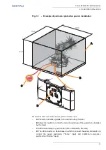
E.DO GRIPPER INSTALLATION
m.
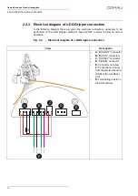
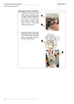
Connect the 2 connectors
M
(CAN SUPP) and
N
(CAN
SIGN) of the CAN network
connection cable and power
supply cable (included with
e.DO Gripper), coming from the
last Robot joint, to the related
connectors present on the e.DO
Gripper electronic board (PCB),
as shown in the figure.
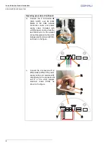
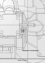
n.
Connect the 2 connectors
P
(2
PIN) and
Q
(4 PIN) of the power
supply cable and resistance
R
respectively to the connectors
S
and
T
of the e.DO Gripper
electronic board (PCB), as
shown in the figure.
Operating procedure (Continued)
M
N
A
B
BUS IN
BUS IN
A
C
BUS OUT
BUS OUT
SUPPLY
T
P
Q
R
S
Summary of Contents for e.DO
Page 27: ......