Colortac SmartLF Ci 24C Installation & Operating Manual Download Page 10

10  

        Colortrac SmartLF Ci 24 / Ci 40 Installation and Operating Manual 


PAS171                                                                                                                      P/N: P005500 Colortrac Ltd © 2010  


CHAPTER 2 PREPARING THE SCANNER AND SOFTWARE 

2.1 Connecting the power and interface cable 


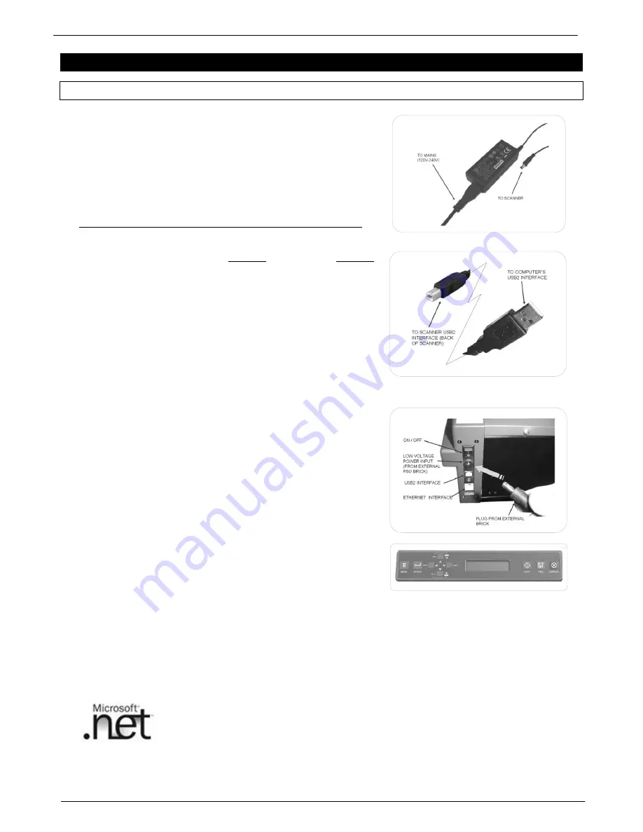
Start by locating the external power supply brick that is made 
up from two parts 

– a cable and a transformer.  The mains 

cable part should already be terminated with a mains 
connector plug suitable for your country.  If the cable is not 
correct contact your supplier.  Plug the opposite end of the 
mains cable into the brick and then push the small round plug 
into the corresponding input socket on the back of the Ci 
scanner. 


THIS INSTALLATION ASSUMES A USB2 DATA CONNECTION 


TAKE CARE TO CONNECT THE POWER LEAD TO THE POWER 
SOCKET ON THE BACK OF THE SCANNER 


The order of connection sockets on the back of the scanner 
from top to bottom is: 


1.  POWER SWITCH 

– ON/OFF 

2.  POWER SUPPLY SOCKET 

3.  USB2 CONNECTION SOCKET 

4.  ETHERNET CONNECTION SOCKET 


Now locate the supplied USB2 interface cable (exact design 
may vary from that shown).   Connect the smaller end to the 
scanner.  Do not connect the larger end of the USB2 cable to 
the computer yet. 


NOTE #1: DO NOT SUBSTITUTE THIS CABLE WITH A LONGER ONE OR 
THE PERFORMANCE OF THE SCANNER MAY BE AFFECTED 


NOTE#2: ALWAYS FIRST INSTALL THE SCANNER USING THE USB2 
INTERFACE. IF YOU WISH TO USE THE ETHERNET CONNECTION THE 
NECESSARY CONFIGURATION STEP ARE DESCRIBED FURTHER ON IN 
THIS MANUAL.


Now switch on the scanner using the rocker switch on the back of 
the scanner.  The liquid crystal display (LCD) should now light up 
and display the word „Initialising‟.  After about 30 seconds this will 
change to display the name of the scanner (Ci) and the firmware 
level. If a document is loaded the display will change to the word 
„READY‟. 


Start up Windows on the computer that will be used with SmartLF Ci. Wait for Windows to finish loading before 
proceeding to the next section. 


See section 7.3 for more information on the minimum PC specifications  


The Windows  .NET Framework environment 


The Colortrac SmartLF All-in-One software application has been created using 
Microsoft .NET.  This means the connected Windows computer should be upgraded 
if required by installing .NET Version 2.0 or later.  Some newer versions of Windows 
come pre-loaded with Microsoft .NET. 
 

SmartLF  Ci  is  designed  for  use  with  Microsoft Windows  Vista, Windows  7  or  Windows  XP  (Home  or  Professional) 
with the latest Service Pack (SP) upgrade.  Colortrac advise that the .NET Framework is also installed  by XP users 

Summary of Contents for SmartLF Ci 24C

Page 1: ...P N P005500 INSTALLATION OPERATING MANUAL FOR SmartLF Ci 24 40 Technical Document Scanners MODEL Ci 24E Ci 40E Ci 24C Ci 40C Ci 24M Ci 40M S N Version 3 5 August 2010...

Page 2: ...THE SCANNER THIS WILL MAXIMISE IMAGE QUALITY p 18 FOR DOCUMENTS THICKER THAN THE STITCH TARGET USE THE PAPER WEIGHT CONTROL p 25 TO COMPLY WITH ENERGY SAVING LEFT UNNATTENDED THIS SCANNER WILL ENTER S...

Page 3: ...symbol is intended to alert the user to the presence of dangerous voltages within the power supply that may be of sufficient magnitude to constitute a risk of electric shock to persons Do not attempt...

Page 4: ...th scanner interface cable Cables box 1 10 Normalisation Target in paper wallet Main box 1 11 Automatic Stitch Target in paper wallet Main box 1 12 Manual Stitch Target pdf file Installation CD 1 Chec...

Page 5: ...20 3 12 Copying using SmartLF All In One 21 3 13 Document size markings of the Ci 21 3 14 Working with clear transparent originals 21 3 15 Scanning double sided originals 21 3 16 Media thickness compa...

Page 6: ...ships polythene wrapped in a single skinned box It is advisable to prepare a desk surface or similar area capable of taking the weight of the scanner You will need an assistant to help you lift the s...

Page 7: ...red tab and carefully lifting the tape up and away from the scanner Remove both tapes completely The tapes cannot be reused and should be disposed of 1 5 Attaching the Control Panel Overlay if necessa...

Page 8: ...t roller Always switch the scanner off before opening the lid for inspection or maintenance Ensure that the scanner is secured to the floor stand or resting on a table before opening the lid With two...

Page 9: ...each latch button pops back up again The lid is now closed and the scanner is ready for operation WARNING Always ensure that both sides of the lid have closed properly Make sure that nothing has been...

Page 10: ...BSTITUTE THIS CABLE WITH A LONGER ONE OR THE PERFORMANCE OF THE SCANNER MAY BE AFFECTED NOTE 2 ALWAYS FIRST INSTALL THE SCANNER USING THE USB2 INTERFACE IF YOU WISH TO USE THE ETHERNET CONNECTION THE...

Page 11: ...T SMARTLF Ci AND AUTOMATICALLY BEGIN RUNNING THE WINDOWS HARDWARE WIZARD HAVE THE COLORTRAC SMARTLF Ci SOFTWARE INSTALLATION CD READY Windows will now ask for the driver Insert the CD now WAIT for a f...

Page 12: ...er is plugged into the computer Windows will identify the USB Universal Serial Bus device as SmartLF Ci and automatically load this driver The scanner can be plugged and disconnected freely like any r...

Page 13: ...tton to install the SmartLF SCAN COPY EMAIL software 4 Click the Ethernet driver button to install the Ethernet driver which allows the scanner to be used via a Gigabit network Once the installation i...

Page 14: ...y into the scanner opening until resistance is met inside the scanner The document must find its load point BEFORE the automatic loading sequence takes over and begins to stage the document At documen...

Page 15: ...is only possible when the SmartLF All In One software is running The panel display will show the word Scanning during movement of the document through the scanner REMOVING A LOADED DOCUMENT CORRECTING...

Page 16: ...Re pressing the COPY or FILE or EMAIL software icons will suspend this scanner operation ScanWorks software Pressing the panel FILE lid panel button will start this scanner operation under remote cont...

Page 17: ...n then pressing ENTER jumps to the option configure stage The Ethernet parameters can be adjusted using the FWD BACK PREV and NEXT buttons Pressing ENTER saves the adjustment and returns the operator...

Page 18: ...Ci is designed to make scanning to file scanning to copy and scanning to email extremely simple to achieve Note that Colortrac recommend the emailing function be used for black and white TIFG4 techni...

Page 19: ...ugh the Windows Scanners and Cameras icon that is located in the Windows Control Panel Refer to Section 3 04 3 07 Setting the scanner color modes COLOR GRAYSCALE BLACK AND WHITE SPEED CONTROL SmartLF...

Page 20: ...o Size can be affected by the type of media loaded in SmartLF Ci For example transparent or non square media may fail to auto size correctly Although SmartLF Ci does not allow custom paper size scanni...

Page 21: ...size scan and auto size scan clear and opaque media Clear acetate drawings will often produce betters results when used with a white backing sheet A scanning wallet with an integral white backing she...

Page 22: ...r s internal paper roller should be cleaned with a damp clean lint free cloth It may be necessary to use a solvent free foam cleaner or other cleaner compatible with EPDM ethylene propylene diene M cl...

Page 23: ...ion RIGHT picture shows a falling stitch problem at the CIS1 CIS2 intersection 4 4 1 Running the automatic stitch routine Load the Automatic Stitch Target included into the scanner face up and centred...

Page 24: ...setting s into scanner calibration memory Rescan the Manual Stitch Target re inspect and make further adjustments as required L R adjustment Make alterations to restore a diagonal line at all sensor...

Page 25: ...erial Number box type in the 8 digit number printed on the label attached to the back of the scanner Now select the model you wish your unit to be upgraded to using the Desired Model scroll bar Press...

Page 26: ...nner is now ready to scan with heavier media NOTE AUTO STITCH changes to the correct setting automatically 4 7 Controlling the Power Save Timer Sleep Mode Ci is equipped with a Power Save Timer that p...

Page 27: ...vailable in a fixed address range This will ensure that a PC which will often be configured to boot and connect dynamically under DHCP will not randomly choose the same IP address as the scanner If in...

Page 28: ...d Data ports Press OK Exit the Ci Utilities application Using Ethernet with Ci Utilities Turn off the scanner Remove the USB2 cable Insert the Ethernet cable Switch the scanner ON Start Ci Utilities t...

Page 29: ...Ethernet radio button Now click the Set IP Address button and enter the IP address and ports These should be the same as those already used in Ci Utilities Exit SmartLF All In One Switch the scanner O...

Page 30: ...r ON Restart ScanWorks If an Ethernet scanner enters Sleep Mode when ScanWorks is not in use restarting ScanWorks will automatically wake the scanner 5 7 Setting and altering the IP settings CopySmart...

Page 31: ...ying to use Ethernet but I think the USB interface is still being used Cause Fix The USB interface is the default connection and the scanner will always use this even if the Ethernet connection has be...

Page 32: ...where there should be white Cause Fix The large white roller or drum in the scanner may need to be cleaned Transparency scanning relies on reflected light returning from the roller to the sensors SWI...

Page 33: ...tible with SmartLF Ci 5 USB2 Gigabit interfaces are mandatory requirements for SmartLF Ci Slower interfaces will cause slow scan speeds and possible SmartLF Ci malfunction See the latest computer spec...

Page 34: ...ils of your supplier here Company Contact Telephone 7 5 DECLARATION OF CONFORMITY Manufacturer Colortrac Ltd 3 5 Brunel Court Burrel Road St Ives Cambridgeshire PE27 3LW United Kingdom Details of Elec...

Page 35: ...s equipment in a residential area is likely to cause harmful interference in which case the user will be required to correct the interference at their own expense UL Certification This product has bee...

Page 36: ...Colortrac Ltd makes no warranty claims with respect to this documentation and disclaims any implied warranties of merchantability or fitness for a particular purpose The information contained in this...

Page 37: ...rac SmartLF Ci 24 Ci 40 Installation and Operating Manual 37 PAS171 P N P005500 Colortrac Ltd 2010 7 6 External dimensions Units inches mm Dimensional accuracy 5 mm 32 7 832 48 5 1232 8 195 7 1 181 10...

Page 38: ...IS Dual 2D extra long life LED light system for optimum object illumination and instant on scanning capability Optics in CIS Solid state fibre optic rod lens with 1 1 object sensor magnification User...

Page 39: ...he optional Colortrac ScanWorks software 6 Languages supported Arabic Chinese Traditional English French German Italian Japanese Korean Portuguese Russian Spanish 7 Microsoft WIA STI is specified for...

Page 40: ...lance 22 H hardware wizard Windows 11 I INSTALLATION CD 11 L language overlay 7 left right L R stitching 24 loading a document technique 14 loading a document into the scanner 14 loading and running C...

Page 41: ...S171 P N P005500 Colortrac Ltd 2010 T thick media working with 21 U upgrading scanner model 25 USB2 dynamics identifying device 13 utilities password 23 W WEEE Waste Electrical Electronic Directive 35...

Reviews: