035-17468-001 Rev. A (801)
Unitary Products Group
23
CONVERSION FOR HORIZONTAL APPLICATIONS
Remove the condensate trap and its mounting bracket from
the unit side panel. Remove all drain hoses.
Reinstall the trap/bracket on the side panel which will be on
the bottom when the unit is located horizontally. Use the orig-
inal mounting screws.
Refer to Figure 35 for hose locations and Table 7 on Page 23
for hose cut lengths. All hoses are identified as shown in Fig-
ure 35.
For horizontal left airflow (inducer and vent low) or horizontal
right airflow (inducer and vent high), install condensate drain
hoses as follows:
RIGHT AIRFLOW (Inducer High) - Three hoses are required.
Hoses are supplied with furnace. Refer to Figure 35 and
Table 7 on Page 23 for application.
LEFT AIRFLOW (Inducer Low) - Two hoses are required.
Inducer outlet to trap is supplied. Condensate pan to trap
must be field supplied using 5/8” I.D. hose material. Refer to
Figure 35 and Table 7 on Page 23, for hose placement and
sizing.
Drain Connection:
The following steps apply to all models.
1.
It is recommended that either 1/2” or 3/4” PVC or equiva-
lent pipe be field installed as drain pipe. The condensate
piping may be tied together with the air conditioning con-
densate drain if the air conditioning condensate drain
line is trapped upstream of the tie-in and the combined
drains are constructed of the same material.
2.
All pipe joints must be cleaned, de-burred and cemented
using PVC primer and cement.
3.
The furnace contains an internal trap. Therefore, no
external trap should be used.
4.
If a condensate pump is used, it must be suitable for use
with acidic water.
5.
Where required, a field-supplied neutralizer can be
installed in the drain line, external to the furnace.
NOTE:
The condensate drain from the furnace may be con-
nected in common with the drain from an air conditioning coil
if allowed by local code. Follow the instructions with the coil
for trapping the drain.
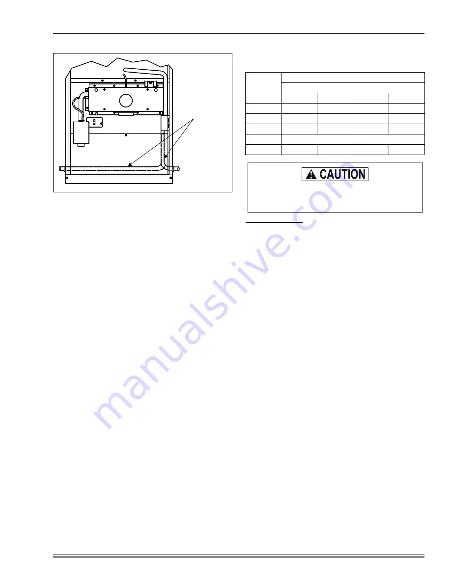
FIGURE 34 :
Downflow/Horizontal Models
CONDENSATE
TRAP TUBING
Table 7:
HORIZONTAL CONDENSATE DRAIN HOSE
SIZES - MODELS P*DH / FG9-DH / G9T-DH
DIM.
CABINET SIZE (IN.)
RIGHT AIRFLOW (INDUCER HIGH)
14-1/2
17-1/2
21
24-1/2
A
4-1/2
4-3/4
3-1/2
5-1/4
B
7-1/2
10-1/2
14
17-1/2
C
13-1/2
16-1/2
20
23-1/2
LEFT AIRFLOW (INDUCER LOW)
D
3-3/8
3-1/4
3-1/4
3-1/4
Plug all unused condensate trap, condensate pan
and inducer drain connection points using plugs
provided.


