9
Figure 5
7.
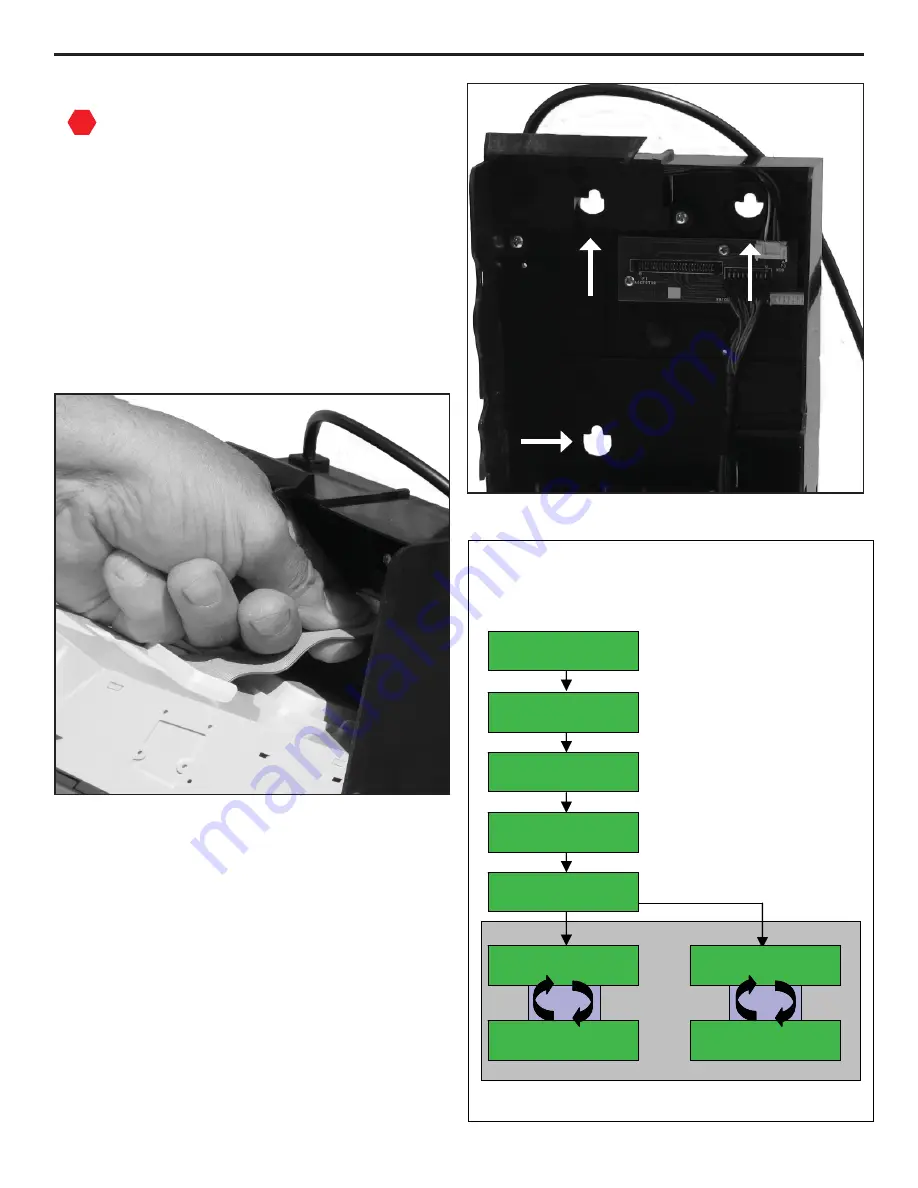
Plug the changer harness into the vending
machine.
Verify steps 1 to 7 are completed
correctly
.
8.
Apply power to the vending machine.
9.
The changer will power up, and then
perform and auto-test of all systems. For
the Guardian E6, the status indicator light
will be green when the unit is operational
and ready for use. For the Guardian 6000,
the display will begin cycling in a steady
state mode as shown in Figure 7.
STO P
SECTION 2: INSTALLATION & SETUP
Figure 6
Steady State Mode
Power Up Sequence
Power Up Sequence
Typical User Display Messaging
• S how s current versions of
softw are and hardw are.
• P erform s self-diagnostics of
system s. If there are errors,
recom m endations are given.
• S elf-diagnostics com pleted
& all system s functional.
• C urrent tube configuration.
N ote: S om e G uardian m odels m ay show different m essaging.
S W : v1.1 v1.1
H W : v1 M D B
C hecking
D iagnostics
D iagnostics O K
D 05¢ E 25¢ F25¢
A 25¢ B 10¢ C 05¢
S tatus: O K
Tubes = $29.15
A dd
$
4.85
Float =
$
34.00
Loop
Loop
G uardian 6000
S tatus: O K
Tubes = $29.15
Float D isabled
Loop
Loop
• Intro screen.
See Figure 16 for details on Steady State Mode messages.
Float Mode Off
Float Mode On
Figure 7


