7
2 Installing the In-Sight 1000
In this section…
2.1 Connecting the In-Sight 1000.................................................................................7
2.2 Installing In-Sight PC Host Software ....................................................................13
2.3 Adding the In-Sight 1000 to a Network.................................................................14
2.4 Logging On to the In-Sight 1000 ..........................................................................19
2.5 Changing In-Sight 1000 Network Settings ...........................................................20
2.1 Connecting the In-Sight 1000
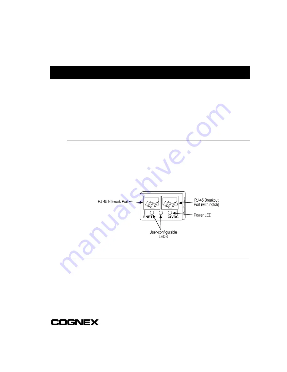
The In-Sight sensor has two RJ-45 connector ports opposite the lens mount, as shown
in Figure 2-1: the Network port (left, labeled
ENET
) and the Breakout port (right,
labeled
24VDC
). The Network port provides the Ethernet connection for network
communications. The Breakout port supplies connections for power, I/O, and serial
communications.
Figure 2-1: In-Sight 1000 Network and Breakout Ports
2.1.1 Connecting the Network Cable
If you are connecting to an Ethernet switch:
1
Plug one of the RJ-45 connectors on a CAT5 straight-pinned cable (yellow if
supplied by Cognex) into the ENET port.
2
Plug the other end of the CAT5 straight-pinned cable into an available port on the
switch.


