background image

mechanicals

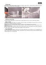
Periodically check all mechanical devices for wear and tear; gears, guides, belts, etc., replacing them if necessary. Ensure the
screws affixing the barndoors are firmly tightened.

electrical components

Check all electrical components for correct earthing and proper attachment of all connectors, refastening if necessary.

dichroic filters

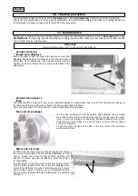
To properly clean the dichroic filters it is necessary to remove the screws which affix the front block of the unit. The front
block of the unit, together with its seal, will come away.
Move each dichroic filter manually to allow access to it and clean with a suitable glass cleaning detergent.

Attention!

Once you have completed the cleaning procedure, make sure that the the seal is correctly replaced when

replacing the front block.
Should you fail to do this, the protection rating of the unit will be compromised, and the internal of the unit may be subject to
the adverse effects of the weather. This may result in damage to these components.

fuse replacement

To replace the fuse it is necessary to remove the two housing plates and open the terminal cover box as described in the
section entitled “Selecting the operating voltage of the transformer” then replacing the fuse as required. Note that the fuse
must be replace with one of similar value.


English

Summary of Contents for Panorama Cyc 1800 Architectural

Page 1: ...Panorama Cyc 1800 Architectural 1st edition october 1999 instruction manual ...

Page 2: ...on of the model and the retailer from whom you purchased your Panorama Cyc 1800 Architectural This information will assist us in providing spare parts repairs or in answering any technical enquiries with the utmost speed and accuracy WARNING the security of the fixture is granted only if these instructions are strictly followed therefore it is absolutely necessary to keep this manual ...

Page 3: ...e 7 4 Connecting the cable between ballast and body 7 5 Mains connection 8 Signal connection 8 1 For automated operation 8 2 For operation via DMX 512 8 3 For multiple Panorama units synchronised without DMX 512 8 4 Connecting multiple Panorama units in synch without DMX 512 9 Powering up 10 DMX addressing 11 DMX 512 signal functions 12 Automated operation 13 Synchronising multiple Panorama units ...

Page 4: ...iency of this product for years to come Open the packaging and ensure that no part of the equipment has suffered damage in transit In case of damage to the equipment contact your carrier immediately by telephone or fax following this with formal notification in writing packing list Ensure the packaging contains 1 Panorama Cyc 1800 Architectural 1 Ballast 1 Instruction manual 8 trapezoidal adjuster...

Page 5: ...good earth connection is essential for proper functioning of the projector Never operate the unit without proper earth connection Protection against ultraviolet radiation 1 Never turn on the lamp if the lense the filters or the aluminium housing is damaged they will only work effectively if the are in good condition Never look directly into the light beam when the lamp is on Safety 1 The projector...

Page 6: ...re part of the mercury vapour family of discharge lamps and must be handled with great care The lamp opera tes at high pressure and the slight risk of explosion of the lamp exists if operated over its recommended life of 500 hours We recommend therefore that the lamp be replaced within the manufacturer s specified lamp life installing the lamp 1 Using a Philips head screwdriver remove the 14 screw...

Page 7: ...DO NOT USE UNDUE FORCE In case of difficulty re read the instructions and repeat the procedure To ensure a uniform beam spread ensure that the lamp is installed with the pinch in the bulb facing the top of the unit Press the lamp firmly into the lampholder to ensure it is seated correctly This will ensure that the lamp is seated correctly in the optical system of the unit If this is not done the b...

Page 8: ...et the operating voltage or frequency for the lamp after the initial ignition of the lamp the unit draws upon initial startup 17 3 Amps You must set the operating voltage or frequency suitable for the country in which the projector is being used 1 Open up the ballast by removing the 4 hex screws with an M 5 allen key 2 Locate the terminal strip marked with a sticker showing 208 230 240 V and 50 or...

Page 9: ... front rear and sides of the projector 2 Using a suitable screwdriver remove the 4 screws which seal the terminal cover 3 Locate the multipole terminal strip and proceed as follows 4 Cable number 15 determines operating voltage connect it to either the 208V 230V or 240V terminal An error in setting the correct operating voltage may cause serious damage to the unit Do not move the cable numbered 8 ...

Page 10: ...tuated in several mounting positions when installed in an exposed area thanks to its IP 44 protection rating To ensure proper installation however there is a simple guideline to follow Panorama Cyc 1800 Architectural allows the beam of light to be tilted in the range of 35 to 75 without having to move any other component except the head of the fixture Mounting the unit incorrectly may cause damage...

Page 11: ...ma Cyc 1800 Architectural and to the primary suspension point is highly recommended to protect against accidental failure however unlikely of the primary suspension point If using an after market safety chain not manufactured by coemar ensure that it is of sufficient rating to hold the weight of the fixture risk of fire Each fixture produces heat and must be installed in a well ventilated position...

Page 12: ...ting that the current draw through the two cores is 9 Amps 7 2 Preparing the cable connecting ballast to body The cable used between the ballast and the Panorama Cyc 1800 Architectural body varies according to the length being utilised For standard lengths up to 10 m properties should be as follows Core 1 Ø 4 mm2 Core 2 Ø 1 5 mm2 Core 3 Ø 1 5 mm2 Core 4 Ø 1 5 mm2 Core 5 Ø 4 mm2 Core 6 Ø 1 5 mm2 Co...

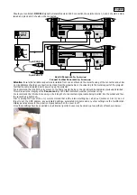
Page 13: ...erminal blocks on both the projector and the ballast which are marked 1 2 3 4 5 6 and GND 8 Insert the multicore cable through the PG 21 connector the larger one and the cable clamp on both the ballast and projector Connect as shown in the diagram 9 The cable clamp should be firmly tightened to ensure protection against water 10 Close up the ballast tightening the 4 bolts with an M 5 hex key Alway...

Page 14: ... essential for the correct operation of the fixture Strict adherence to regulatory norms is strongly recommended Prior to closing up the base of the projector proceed to the connection of the signal cable section 8 and to the internal settings required sections 10 to 14 do not forget to set the DMX address automated functio ning automated program and the other options which may be selected via the...

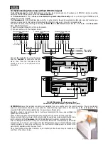
Page 15: ...rchitectural may operate in stand alone mode in the absence of control signal using pre pro grammed colour changing sequence which can be activated by the multi function panel on the unit No incoming signal to the XLR3 sockets should be connected We recommend that the PG 9 entry sockets the smaller be isolated by using plastic material or two short length of uncon nected cable Sealing the DMX IN a...

Page 16: ...SCONNECT FROM POWER SUPPLY BEFORE OPENING A GOOD GROUND CONNECTION IS ESSENTIAL pin1 gnd pin2 data pin3 data pin4 optional pin5 optional dmx 512 in out 3 2 1 AUto auto sequence MA SLlink between fixture AUSP auto speed AUdL auto delay diMM dimmer coLr colour speed LAMP lamp function tESt single ch test function rESE reset rAtE DMX speed HoUr working time in hour LIFE lamp life in hours on MASt mas...

Page 17: ...onnections pls refer to the instructions manual ATTENZIONE ALTA TENSIONE ALL INTERNO DELL APPARECCHIO TOGLIERE TENSIONE PRIMA DI EFFETTUARE QUALSIASI OPERAZIONE UNA BUONA CONNESSIONE DI TERRA E ESSENZIALE WARNING HIGH VOLTAGE INSIDE DISCONNECT FROM POWER SUPPLY BEFORE OPENING A GOOD GROUND CONNECTION IS ESSENTIAL pin1 gnd pin2 data pin3 data pin4 optional pin5 optional dmx 512 in out 3 2 1 AUto au...

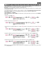
Page 18: ...e will perform a reset function on its internal motors This will last some few seconds after which it will be subject to any external signal from a controller led DMX The DMX led will be static on to indicate that DMX 512 signal is being correctly received If the led is off the projector is not receiving signal check the cabling and the functioning of the controller off on no dmx dmx ok enter menu...

Page 19: ...uld be addressed as 6 a third as 11 and so on until the final unit has been addressed altering dmx addresses 1 Press the or button until the display shows the DMX required the characters in the display panel will flash to indicate that the selection is not stored in memory 2 Press the enter button to confirm your selection the display will stop flashing and the projector will now respond to the ne...

Page 20: ...nal from close to open 8 255 2 cyan proportional proportional cyan control from white to cyan 0 255 3 magenta proportional proportional magenta control from white to magenta 0 255 4 Yellow proportional proportional yellow control from white to yellow 0 255 5 function step lamp off 0 114 motor reset 115 140 lamp on 141 255 Back panel can modify function channel inhibit lamp off 5 function step lamp...

Page 21: ...omated mode will have the lamp turn on immediately and will be unable to have control of their dimmer modified AOO1 C O L R velocità del cambiacolori Velocità di intervento del sistema cambiacolori al variare del segnale DMX selezione tra standard e lenta slow S T R D velocità standard S L O U velocità lenta menu o enter o o enter enter AOO1 A U S P velocità di esecuzione del programma di cambio c...

Page 22: ... the coemar default 5 Adjust the fade time between the colours if you wish to alter from the STRD set as coemar default Note Projectors in automated mode will have the lamp turn on immediately and will be unable to have control of their dimmer modified AOO1 C O L R velocità del cambiacolori Velocità di intervento del sistema cambiacolori al variare del segnale DMX selezione tra standard e lenta sl...

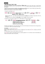
Page 23: ...may be altered from 0 to 55 and relates to the point at which the slave will commence its colour change sequen ce with respect to that being generated by the master For example Synchronising two projectors with AUDL 20 When the Master reaches the 20th colour in its colour change sequence the slaves set to AUDL 20 will begin with the first colour The synchronising continues until the projectors are...

Page 24: ...enter enter enter o o o o o o o o o o o o enter enter enter enter enter enter enter enter enter enter AOO1 D I M M dimmer speed Mechanical dimmer operating time speed on DMX signal variation selection between standard and slow C O L R colour changer speed Colour changing system operating time speed on DMX signal variation selection between standard and slow L A M P lamp function Lamp on off contro...

Page 25: ... each supporting arm of the barndoor leaves you will find a screw loosen this for adjustment 2 Adjust the angle of each leaf to suit your installation 3 After adjusting your leaf position ensure that the screws are securely tightened to avoid sagging 4 In the packaging of the unit are included 8 trapezoidal aluminium pieces these are used to supplement the effect of the barndoor by fitting into th...

Page 26: ...horizontal using the vertical stretch filter D 30 on the vertical axis 50 on the horizontal using no filter To obtain any of the 3 angles other than that offered by the standard filter you should proceed as follows Attention Never look directly into the light beam there is a danger from ultraviolet radiation Prior to undertaking this procedure either turn off the projector or turn on the dimmer 1 ...

Page 27: ...in access to the lamp as described in section 4 Open the rear panel of the unit using the handle placed there for his purpose fans and air passages The fans and air passages must be cleaned approximately every 6 weeks the period for this periodic cleaning will depend of course upon the condi tions in which the projector is operating Suitable instruments for perfor ming this type of maintenance are...

Page 28: ...ilter manually to allow access to it and clean with a suitable glass cleaning detergent Attention Once you have completed the cleaning procedure make sure that the the seal is correctly replaced when replacing the front block Should you fail to do this the protection rating of the unit will be compromised and the internal of the unit may be subject to the adverse effects of the weather This may re...

Page 29: ...mpting any changes electronic calibration Important Note electronic calibration is only possible if the projector is connected to a DMX 512 source menu DIMM dimmer Dimmer alignment CYANcyan Cyan colour alignment MAG magenta Magenta colour alignment YELL yellow Yellow colour alignment END end To end the electronic setting procedure and confirm the recording o o enter 0128 enter o es 0 1 2 0 enter 0...

Page 30: ...ectural are available as replacement spares from your authorised coemar sales agent Accurate description of the fixture model number and type will assist us in providing for your requirements in an efficient and effective manner 19 Spare parts English ...

Reviews: