background image

7


5.2 Menu 2: Program Editing 


In this menu item up to 72 individual programs can be recorded, edited or deleted. The controller is able to store a maximum 
of 1024 program scenes, each with a maximum number 99 steps each.  
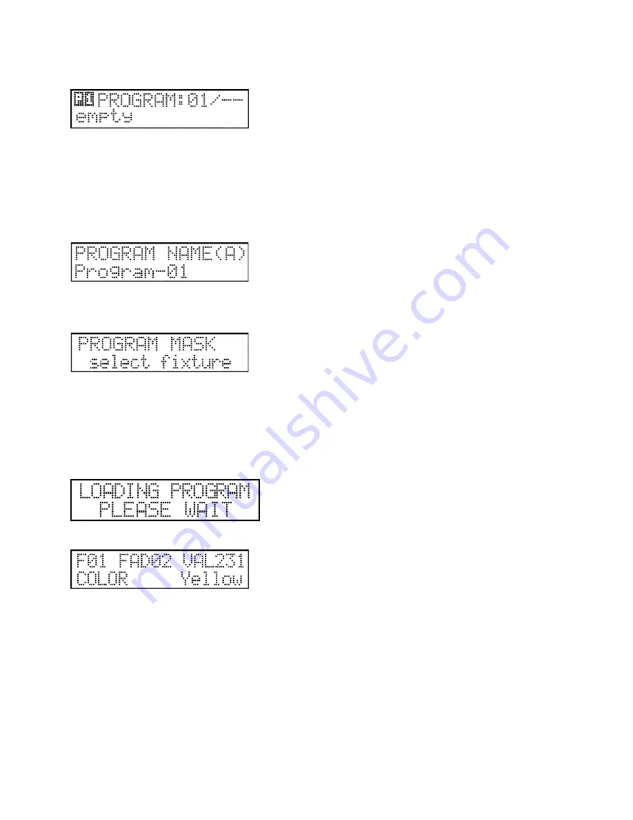
In the top line of the display, the number of the selected program is shown, or if using an existing program, its step number. 
In the bottom line, the program name can be read if it has been created or the text will be ‘empty’ if no name has been 
assigned. 
Select a program with the help of buttons 1-24 and the PAGE shift button. Pressing the ENTER button allows you to move to 
program editing, the first step of which is creating or modifying the program’s name.  
 
Create a program name: 


Create a name using the text keys as previously described in this manual. When finished, press the ENTER button.  
 
Selecting devices: 


You will now need to select which devices will take part in your program. This can be done using the 1-24 buttons. The 
current setup will be displayed on the respective button’s leds. If a LED is flashing, than it is selected. The selected units will 
be on and the unselected off, so it is a very simple task to identify the selected devices on the stage. After selecting a device 
using the buttons, the respective device name is displayed in the LCD display for about two seconds. Selecting two buttons 
simultaneously will select or deselect all buttons between them. 
After selection is complete, press the ENTER button. 
 
Editing programs: 


It may take a few seconds for a program to load, after which time the controller enters program editing mode. 


Summary of Contents for Director 768

Page 1: ...instructions manual 3rd edition January 2007 ...

Page 2: ...5 7 4 Setup Menu 4 Led Setup 17 5 7 5 Setup Menu 5 Language Selection 18 5 7 6 Setup Menu 6 Working Time 18 5 7 7 Setup Menu 7 Software Version 18 5 7 8 Setup Menu 8 Controller Data 18 5 7 9 Setup Menu 9 Menu Code 18 6 Automatic Mode 20 6 1 Function of some operating devices 20 6 2 Launching the programs 20 6 3 Program scene shifting time modification 20 6 4 Control of the head movement and mirror...

Page 3: ...tion and contrast can be set up via the menu When altering parameters of any attached devices information about the changes is displayed 4 FUNCTION buttons Programmable buttons F1 F8 5 SPEED slider sets the program playback speed ranging from 0 3s 5 0s The setup is linear between the two limits the actual value is shown in the display to the thousandth of a second 6 WAIT slider sets the delay time...

Page 4: ... activation mode 4 Controlling the Units The controller addresses attached devices automatically in multiples of 32 The DMX addresses of any attached devices should be set accordingly The addresses can be modified in the UNIT POSITION setup menu Unit nr Dmx addr Unit nr Dmx addr 1 A 1 13 A 385 2 A 33 14 A 417 3 A 65 15 A 449 4 A 97 16 A 481 5 A 129 17 B 1 6 A 161 18 B 33 7 A 193 19 B 65 8 A 225 20...

Page 5: ...o gaining access to the menu The code can be entered via buttons 1 24 After entering the code press ENTER If an incorrect code is entered the controller will give a warning and the ESC button must be pressed in order to recommence the process If you lose or forgot your code you will need to access the PIN code of the controller To gain access to the PIN code you will first need the serial number o...

Page 6: ... potentiometer 5 in this way for example a laid octet can be drawn Initial angle initial position of the shapes can be set with potentiometer 6 drawing will be started in this position Shape drawing can be stopped on a unit it means that if a unit has been drawing a shape so far and now such a shape is starting in which the shape drawing of this unit is set to stop it finishes the unit drawing It ...

Page 7: ... a program name Create a name using the text keys as previously described in this manual When finished press the ENTER button Selecting devices You will now need to select which devices will take part in your program This can be done using the 1 24 buttons The current setup will be displayed on the respective button s leds If a LED is flashing than it is selected The selected units will be on and ...

Page 8: ...o this press the SHAPE button The number of the edited program and scene can be shown in the middle of the upper line of the display In the bottom line the name of the shape assigned to the current step Stop or Without changes captions can be read Without changes means that no shape is assigned to the current step The Stop caption means that shape drawing will cease in the current step If there is...

Page 9: ...sting sequence its step number The bottom line of the display shows the sequence name is one has been created or empty if one has not Select a sequence using buttons 1 24 and the PAGE shift button Press the ENTER button to move to sequence editing Naming sequences Create a name using the text keys as previously described in this manual When finished press the ENTER button Selecting devices You wil...

Page 10: ...umber of the selected preset and OK caption if one exists or free if one does not The bottom line displays the name of the preset if one has been entered Select a preset using the 1 24 buttons and the PAGE shift button Press the ENTER button to move to preset editing mode The first step is to assign a name to the preset Assigning a preset name Create a name using the text keys as previously descri...

Page 11: ...py the preset The display will show information about both source and destination Pressing the F5 ESC button will cause the controller to step back without copying Pressing the F6 ENTER button will confirm the copy 5 5 Menu 5 Record Editing A record is an event which initiates programs and lets them run over a preset timeframe In this menu up to 72 records may be recorded edited or deleted The max...

Page 12: ...ton will cause the controller to step back without copying Pressing the ENTER button will confirm the copy 5 6 Menu 6 Programmable Function Buttons F1 F8 The console has programmable function buttons in F1 to F8 There are many functions which can be assigned to these function buttons In order to assign a function to these buttons see the MENU section Function buttons Below are the functions which ...

Page 13: ...ne a new manufacturer F5 ESC back to setup menu without saving changes F6 ENTER open the list of devices which are produced by selected manufacturer Press F6 ENTER to select a device type from the selected manufacturer s list F1 DOWN scroll down to select a device if there is more than one device in the list F2 UP scroll up to select a device if there is more than one device in the list F4 NEW def...

Page 14: ...TER go forward to the next adjustment SLIDER 12 select numbered characters from 0 to 9 SLIDER 13 select lowercase characters from a to z SLIDER 14 select uppercase characters from A to Z Press F6 ENTER to proceed to assigning sliders to actual channels Assigning the device channel to a slider In the top line of the display the current channel number of the device and the name of the current parame...

Page 15: ...on you can assign an insert value on the prism channel in which case the units will not start to strobe on the push of a button but their prisms will be activated Press the ENTER button to switch the lamp on off Device lamp channel setup If you wish to set a channel to turn the lamp on or off you may do so using the 7th and 8th sliders If you do not require this press the DELETE button Press the E...

Page 16: ... direction of the particular unit assigned to the position can also be seen Mirror directions can be inverted so that mirrors or heads of units installed opposite each can move in the same direction according to settings on the scroll wheel to left In the bottom line of the display the name of the unit assigned to the position is displayed F1 alter the PAN direction of the selected device F2 alter...

Page 17: ...pressing the ESC button returns the controller to the setup menu If modifications have been made the controller requires confirmation prior to saving Pressing the F2 cancel button causes the controller to remain in the menu item pressing the F5 ESC no button causes the controller to return to the menu without saving modifications while by pressing the F6 ENTER yes button causes the controller to s...

Page 18: ...l operating life of the controller is displayed in the bottom line second minute hour Exit the menu item by pressing the ESC button 5 7 7 Setup Menu 7 Software Version In the top line of the LCD display the software version is displayed The bottom line displays the software s issue date is displayed day month year Exit the menu item by pressing the ESC button 5 7 8 Setup Menu 8 Controller Data In ...

Page 19: ...ENTER button If the two entered codes are not the same the controller will display a warning You will need to repeat the procedure Press the ESC button and start again If the two codes match the controller will then ask you to save your code Pressing the ESC button exits without saving Pressing the ENTER button will save your lock code At this point the lock code is activated on so from automatic ...

Page 20: ... using the bank selecting buttons The half intensity flashing indicates that the program with assigned to this channel is running but not in the currently selected bank 6 2 Launching the programs After pushing the PROGRAM button programs can be launched using buttons 1 24 After launching a program its LED will flash indicating that the program is running The display will show the number of the cur...

Page 21: ...oaded the program scene number will increase by one With this mode you can make great effects also with simple programs Try to change in special mode the wait and speed time If the speed time is higher then wait time one of the beam moving when a new beam will start move 6 SCENE mode When pressing the SCENE button shifting of the programmes stops on the actual group and step shifting will happen b...

Page 22: ...ode is available by pressing the FIXTURE button In this mode individual device channels can be altered using the 1 16 sliders and the scroll wheels In this mode the FIXTURE button s LED will illuminate at full intensity indicating that the manual mode is active Devices can be specified using the 1 24 buttons their leds will be flashing If no unit is selected the display will indicate NO UNIT SELEC...

Page 23: ...urrent intensity value as a percentage figure 7 3 Lamp Function The controller is able to turn the fixture s lamp on and off if the device has this functionality available and this has been set to on at installation By holding down the LEFT RIGHT buttons simultaneously the controller moves to lamp mode At this time switch on and switch off values can be sent to the fixtures using buttons 1 16 Pres...

Page 24: ...f soft channels 255 Connectors and plugs DMX connectors A and B For scanners movingheads dimmers and smoke machines Power supply The controller can be operated from a power supply of AC and DC types therefore the linking is not sensitive to polarity The controller should be operated only from such a power supply which is of 12 voltage and can be loaded with at least 500ma PC RS232 connector subd9 ...

Reviews: