Instructions to assemble and install
Edition E0
Page 36 of 69
Confidential and Property of CoeLux S.r.l.
Fig. 28
Installation sequence - Step 11
Fig. 29
21
14
18
9
19
20
22 bis
Page 1: ...ghting equipment CoeLux 45 HC CoeLux 45 HC_P CoeLux 45 HC_P_M Instructions and warnings for assembly and installation CoeLux S r l Via Cavour 2 22074 Lomazzo Como Italy Tel 39 0236714394 www coelux co...
Page 2: ...8 2 2 1 OPERATIONS TO AVOID 9 2 3 PACKAGING HANDLING AND STORAGE 9 2 3 1 UNPACKING 10 2 3 2 HANDLING THE PARTS 10 2 3 3 STORAGE 10 3 PRE INSTALLATION 11 3 1 PERMITTED APPLICATIONS 11 3 2 DESIGNING THE...
Page 3: ...6 assembly of fixing kit 49 6 2 18 STEP 17 49 6 2 19 STEP 18 51 6 3 VENTILATION CONNECTIONS ONLY FOR PROJECTOR 74 00013 01 53 6 4 SUPPORT MACHINES FOR INTERNAL AIR CONDITIONING 54 6 5 CHECKS 54 7 HOW...
Page 4: ...may be changed without prior warning This manual consists of a total of 69 pages annexes 1 1 CONVENTIONAL SYMBOLS USED IN THE MANUAL WARNING This indicates that the operator must pay maximum attentio...
Page 5: ...ician capable of operating the unit prepared to carry out all electrical interventions to adjust maintain and repair Capable of operating on live parts inside electrical cabinets and junction boxes Qu...
Page 6: ...ls arising from the incorrect installation and or use or which differs from what is described in this manual If the rooms are subject to particularly difficult environmental conditions a daily rise in...
Page 7: ...62 01 74 00062 01 74 00063 01 74 00063 01 Projector cooling Active Passive Passive Passive Passive Metal BOX 74 00004 01 74 00004 01 74 00004 01 74 00004 01 74 00004 01 Panel 03 00001 01 03 00001 01 0...
Page 8: ...product or how to operate it in general may depend on the choices made during assembly and or installation The product is not a toy and must be kept out of children s reach Install the product where c...
Page 9: ...e vents or heat dissipation outlets Use inflammable liquids near the equipment Install or repair without using qualified personnel Walk on the system lean on it or hang on to it throughout the unit s...
Page 10: ...CoeLux S r l 4 Proceed to assemble as indicated in Chapter 4 5 Save and dispose of all the packaging material in compliance with the measures of the laws in force 2 3 2 HANDLING THE PARTS All the com...
Page 11: ...ems are used in environments subject to specific legislation undergrounds tunnels etc an assessment must be made by competent personnel Contact CoeLux S r l to receive guidelines for any specific proj...
Page 12: ...of tools required to install the 45 HC systems but which are not supplied in the assembly kit Tool Quantity Notes Image Impact drill 1 With bits to drill concrete reinforced concrete and metal Screwd...
Page 13: ...ggles shoes gloves etc Always follow the legislation in force in the country of installation Ladder compliant with the legislation in force At least 2 Height 3 5 m Screwdrivers scissors cutters pliers...
Page 14: ...69 Confidential and Property of CoeLux S r l Laser level 1 Tape measure 1 Silicone gun with transparent silicone cartridge 1 Anti mould acrylic silicone Electric extension cable At least 1 Triple pole...
Page 15: ...ategory 3 or 4 1 Foldable gazebo as required see Chapter 5 1 Minimum dimensions 5 x 4 m Platform trolley to move the assembled equipment At least 4 Dark Box Support At least 6 Please read Chapter 7 AS...
Page 16: ...TY DISTANCES AND VOLUME For the system to operate at its best the louvre thermally coupled to the LED source needs to exchange air with the surrounding environment If the air within the false ceiling...
Page 17: ...C systems must be fastened to the existing structure by qualified personnel selected by and under the responsibility of the installer or user according to the safety measures in force in the place of...
Page 18: ...ystem Fastening of L shaped profiles and threaded bars Ceiling fastening plate with 2 anchor points 73 00153 01 140x60x5 plate welded to the threaded M12 bar with 11 mm fastening hole 73 00156 01 M10...
Page 19: ...ning instructions to enable you to assemble even in very dusty environments These instructions envisage the use of a specific kit supplied together with the product cleaning kit No 38 00002 01 The kit...
Page 20: ...special care Delicately remove any dirt so as not to damage the optical surface and ensure the best performance We recommend you begin by cleaning gently and then proceed with more decisive aggressive...
Page 21: ...hapter 5 INITIAL CLEANING The following figure shows an exploded diagram of the structure of the 45 HC systems and gives the names of the main parts A Silica gel compartment door B Lamp C Caps D Wedge...
Page 22: ...es must be removed from their packaging outside the clean chamber whereas they have to be assembled inside the latter When you have completed the cleaning instructions open the wooden box containing t...
Page 23: ...oor approximately 45 cm while it is being assembled to facilitate assembly operations The picture below shows an example of a support structure which CoeLux S r l can supply on request It also gives t...
Page 24: ...l 6 2 2 STEP 2 Use the screws and M8 nuts supplied for this size of bolts we advise using a 20 Nm tightening torque to assemble the lower panels 1 CoeLux PN 73 00001 01 2 PN 73 00002 01 3 PN 73 00003...
Page 25: ...erimeter of one side Place a thin strip of transparent silicone on the inner edge of the frame 5 PN 73 00005 01 highlighted in the close up below and in Figure 6 Take care the transparent strip of sil...
Page 26: ...PN 73 00008 01 and fasten it on to the lower panels 1 2 4 and to the rear panel 7 PN 73 00007 01 Use the screws and M8 nuts supplied to assemble the vertical panel 9 PN 73 00009 01 and fasten it on to...
Page 27: ...ed to assemble the large upper panel 13 PN 73 00013 01 on to the vertical panels 7 8 9 Use the screws and M8 nuts supplied to assemble the small upper panel 14 PN 73 00014 01 and fasten it on to the v...
Page 28: ...ps of pre stressed steel wire on the edge of the window The folded edges 16A of the vertical divider 16 PN 73 00016 01 must be inserted inside the already assembled panels i e towards the CoeLux panel...
Page 29: ...Instructions to assemble and install Edition E0 Page 29 of 69 Confidential and Property of CoeLux S r l Fig 16 Installation sequence Step 6...
Page 30: ...7 and to the vertical panel 9 Use the screws and M8 nuts supplied to assemble the vertical panel 21 PN 73 00021 01 and fasten it on to the lower panel 17 and to the vertical panel 8 Use the screws and...
Page 31: ...tressed steel wire on the edge of the window The folded edges of the vertical divider 23 PN 73 00023 01 must be inserted inside the already assembled panels i e towards the CoeLux panel aperture Check...
Page 32: ...the vertical panel 19 Use the screws and M8 nuts supplied to assemble the other vertical panel 25 PN 73 00025 01 and fasten it on to the lower horizontal panel 24 PN 73 00024 01 and to the vertical p...
Page 33: ...cotton gloves provided in the cleaning kit to handle the mirrors Then mask the entire perimeter of the small mirror 28 PN 03 00002 01 by gluing the black insulation tape over the bevelled edge as sho...
Page 34: ...small mirror When you have finished cleaning slot the small mirror 28 PN 03 00002 01 in the opening prepared on the vertical dividing panel 23 with the reflecting part facing upwards until it clicks i...
Page 35: ...large upper mirror 32 PN 03 00003 01 inside the frame 22 the reflecting part must face towards the inside of the box and use the M8 screws and nuts supplied to fasten it with the 4 brackets 33 PN 73...
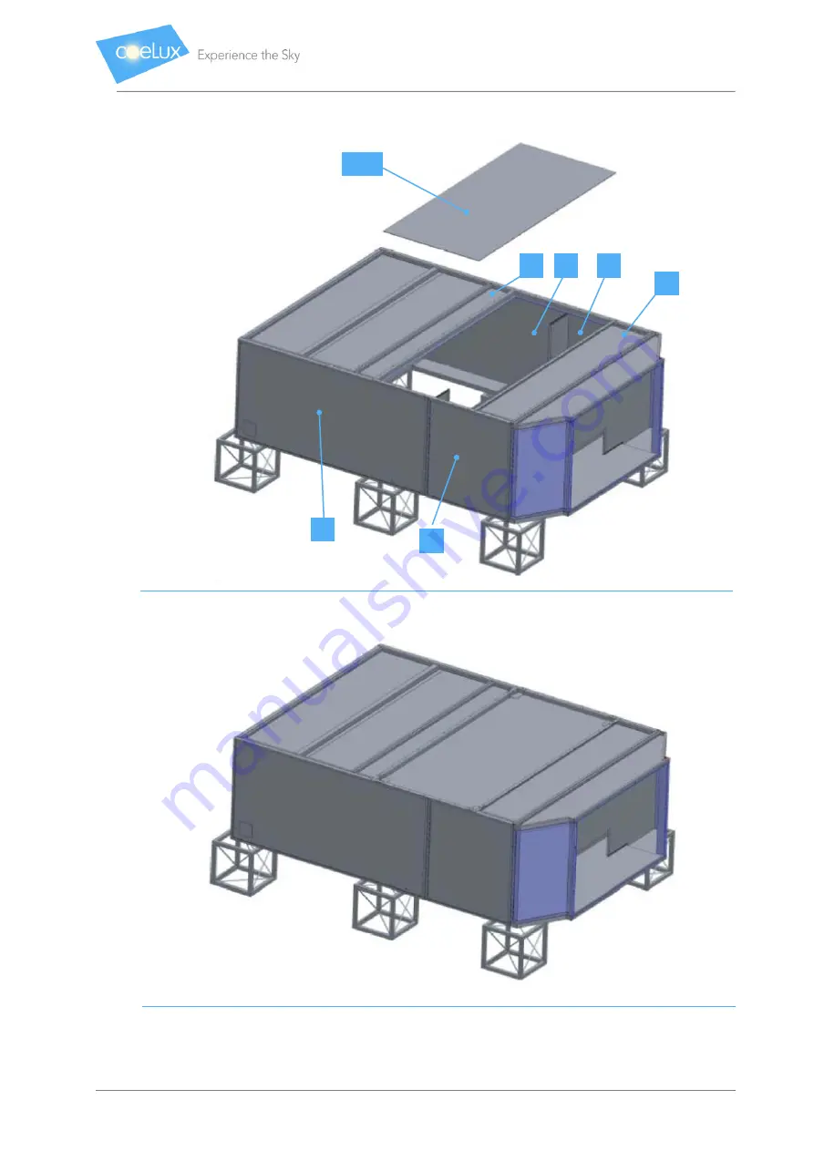
Page 36: ...nstructions to assemble and install Edition E0 Page 36 of 69 Confidential and Property of CoeLux S r l Fig 28 Installation sequence Step 11 Fig 29 Installation sequence Step 11 21 14 18 9 19 20 22 bis...
Page 37: ...01 and fasten it on to the two vertical triangular panels 30 and 31 and to the upper panel 29 PN 73 00029 01 Use the M6 screws supplied to assemble the closing caps 10 PN 73 00010 01 Use the M6 screws...
Page 38: ...supplied to fasten the sub group assembled in Step 12 to the main body When you open the latter make sure all the elements are correctly aligned and no object or dirt is visible along the optical pat...
Page 39: ...ojector 36A PN 74 00013 01 out of its packaging box and use the four M6 screws supplied to fasten it to the fastening frame 35 PN 73 00035 01 Use ALL 8 M6 screws supplied to fasten this sub group to t...
Page 40: ...2 hose clips PN 36 00023 01 CAUTION The exclusive installation of air manifolds and insulated pipes is mandatory in order to maintain UL and CB certification 6 2 14 2 MODIFICATION OF STEP 14A Use the...
Page 41: ...ll the manifolds Now cut the insulated pipe PN 36 00022 01 into 2 equal parts each measuring 2 metres 48 and use the hose clips 49 PN 36 00023 01 to connect them to the round manifold terminals Once y...
Page 42: ...e cable gland to the junction box as shown in Figure 40 D Insert the external power supply cables into the cable gland E Take out the rubber cable glands from the branching terminal board Figure 41 in...
Page 43: ...CoeLux S r l Fig 39 Rear view of the projector 74 00013 01 Fig 40 Cable gland installation diagram Fig 41 Branching terminal board to connect the mains supply cables Junction box M16 galvanised washe...
Page 44: ...d install Edition E0 Page 44 of 69 Confidential and Property of CoeLux S r l Fig 42 Sketch to show an example of the terminal board supplied Fig 43 Completed electrical connections to the projector 74...
Page 45: ...he centring pins 50 red circle in Figure 46 to install the projector directly on to the tilted panel 29 Figures 44 and 45 Then fasten it with the 4 M6 captive screws 51 on to the support plate Figure...
Page 46: ...blocking the frame 55 on to the projector 36B Place the moon module over the 4 holes 56 and reinsert the entire cable inside the aperture on the projector Use the 4 M6 screws with washers 54 to fasten...
Page 47: ...packaging for the projector 74 00062 01 74 00063 01 is a bag with N 2 M16 cable glands N 4 M16 galvanised washers N 2 M16 nylon nut Fig 47 Rear of the projector 74 00062 01 74 00063 01 A Open the lid...
Page 48: ...l Fig 48 Power supply terminal board inside the junction box 6 2 16 STEP 15 Then take the bag containing the silica gel open it and insert the 18 little bags inside the compartment below the projector...
Page 49: ...mately 300 kg to lift the 45 HC products While it is being lifted the box must rest on at least three different points Make sure it is as horizontal as possible and is not subjected to sudden movement...
Page 50: ...u may need to use more than one cotton cloth for this stage all supplied in the cleaning kit Fig 51 Lifting points for CoeLux 45 HC Use the screws and M8 nuts supplied to assemble the sub group on to...
Page 51: ...rs mounted on the ceiling Paragraph 4 3 inside the special holes on the plates 73 00152 01 mounted on the dark box Fig 54 and Fig 55 Fig 54 Anchor system fastening plates on the dark box M12 threaded...
Page 52: ...Instructions to assemble and install Edition E0 Page 52 of 69 Confidential and Property of CoeLux S r l Fig 55 Recommended anchor system See Figure 54...
Page 53: ...solution for the layout of the ventilation pipes inside the false ceiling CAUTION The dimensions A B C and D are functional to the design of the room and can be calculated according to the architectu...
Page 54: ...nsure the equipment is working and enable any anomalies to be corrected WARNING To avoid being dazzled do NOT look inside the window when the unit is being switched on Switch on the unit and visually...
Page 55: ...er image etc which are nevertheless temporary and normal we recommend you do not stare at the light source for a long time and do not allow people with limited cognitive ability or mobility children e...
Page 56: ...he table below shows the preset scenarios Scene Level Modifiable Fading 1 75 Yes Yes 2 100 Yes Yes 3 MOON No No 4 Off Yes No 5 55 Yes Yes 6 70 Yes Yes 7 85 Yes Yes 8 100 Yes Yes Tab 5 Versions of 45 H...
Page 57: ...nt temperature If you need to remove parts of the unit for maintenance restrict these to the essential minimum Reassemble the parts immediately after the intervention Never leave tools equipment or ot...
Page 58: ...so at an angle WARNING The installer is always responsible for fastening the 45 HC systems to the existing structure It must be carried out by specialised personnel who comply with the safety measures...
Page 59: ...esponsible for the structural certification of the new suspension system CoeLux S r l declines any liability for the use of any alternative suspension system to the one offered Application of a 12 mm...
Page 60: ...least 1 6 kN Fig 61 Close ups D1 and D2 shims for the tilted dark box suspension system LIST OF THE SUSPENSION ELEMENTS measurements in mm element T1 shim x20 element T2 threaded M12 bar VAR element T...
Page 61: ...5 angle profile tilted x2 Fig 63 Elements P1 A1a A1b A2a and A2b LIST OF BOLTS AND PLUGS M8 bolt 8 8 x8 M10 bolt 8 8 x10 Fig 64 M8 and M10 Bolts P1 A1 a Hole 10 2875 2274 20 Slot 10x12 2234 20 50 1855...
Page 62: ...tial and Property of CoeLux S r l Fig 65 Chassis layout and elevations Elevation 1 Elevation 2 Layout Element A1a Element A1a Element A1b Element A3 Element A3 Element A3 Element P1 Element P1 Element...
Page 63: ...APPLICATION This cleaning procedure is needed only in extraordinary cases in which once the mirrors have been removed from their packaging during product installation the reflecting surface is not pe...
Page 64: ...point it at the mirror at a 45o angle of incidence from a distance of at least 1 5 m The other two operators must analyse the surface of the mirror for approximately 30 seconds holding it vertically...
Page 65: ...Instructions to assemble and install Edition E0 Page 65 of 69 Confidential and Property of CoeLux S r l Fig 67 Case A Fig 68 Case B...
Page 66: ...the centre of the mirror very dirty mirror Find the following materials ethyl alcohol 95 ammonia demineralised water and proceed as follows Take a small quantity of ammonia and dilute it in demineral...
Page 67: ...CTS IN THE GLASS SURFACE DEFECT PHOTOS ACCEPTABILITY Thick dirt very opaque glass surface Case C Widespread dirt surface with an opaque layer visible without the help of the projector Case C Ring mark...
Page 68: ...se B if they do not disappear Case C Build up of dust area with a light build up of dust visible thanks to the use of the projector Case B 9 2 4 3 DEFECTS IN THE SILVER SURFACE DEFECT PHOTOS ACCEPTABI...
Page 69: ...a summary is also prohibited This manual reproduces the technical status at the time of printing The company reserves the right to modify not only the text images and data contained herein but also in...