HPF9000-OM (V1.8)
HPF-9000 PRODUCT MANUAL
2-9
Installation and Setup
Installing Rear I/O Modules and Cards
Installing Rear I/O Modules and Cards
Rear I/O Module Installation
1.
On the frame, determine the slot in which the card is to be installed.
2.
In the mounting area corresponding to the slot location, install
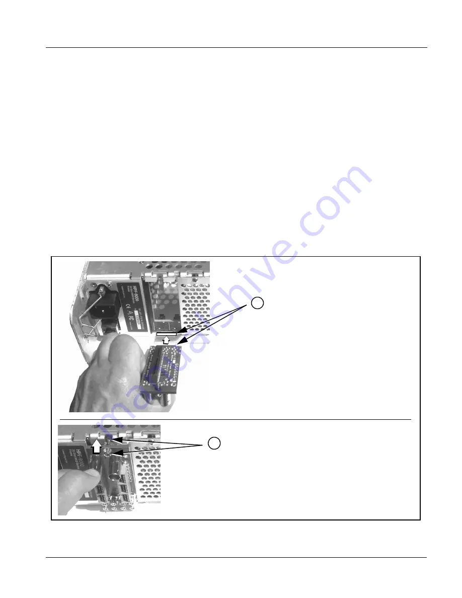
Rear I/O Module as shown in Figure 2-7.
Note:
Note that with all rear modules (except for “split” types), an offset of the card
edge connector results in the loss of one or more adjacent slots of the two or
more slots consumed by the rear module.
Also note that when installing a Fusion3G
®
card equipped with an expansion
card (used for some options such as analog video/audio), the base card
occupying slot n results in the expansion card occupying slot n+2, or 2 slots
to the right. (Example: with base card in slot 18, expansion card mates with
slot 20.)
Note these considerations when planning card locations within the frame. See
Frame Card Capacity in Chapter 1. Introduction for more information.
Figure 2-7 Rear I/O Module Installation
Align and engage mounting tab on Rear
I/O Module with the module seating slot
on rear of frame chassis.
Hold top of Rear I/O Module flush against
frame chassis and start the captive screw.
Lightly tighten captive screw.
1
2


