


Chapter 3. Installation
98
Smart 110V Power Supply Installation
Following is the procedure for installing the Smart 110 V AC power supply. Follow the steps in
the order given. Refer to Figure 3-26 for jumper locations on the power unit.
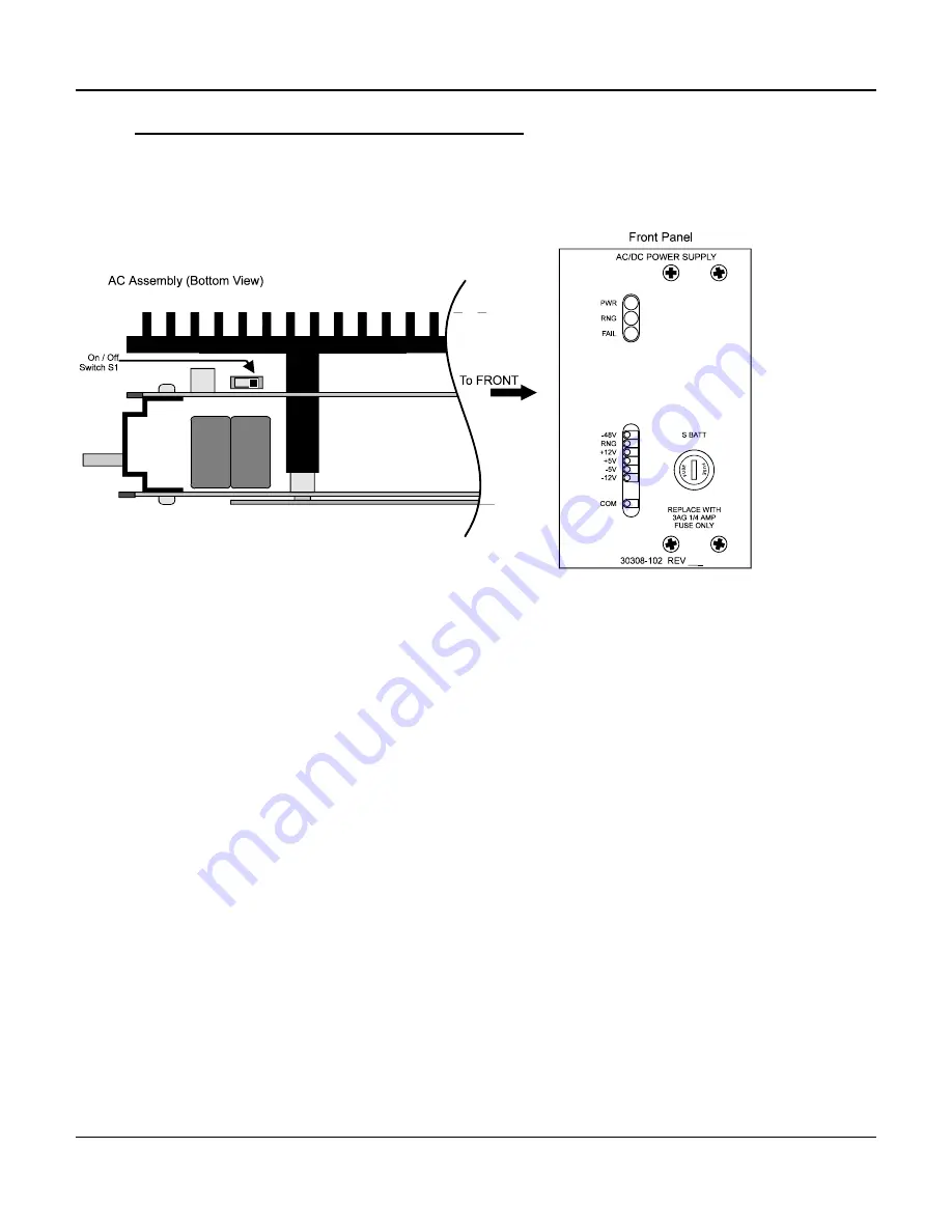
Figure 3-32. Smart 110 V AC Power Unit
(Front Panel and Bottom View)
1. Set Switch S1 to enable or disable the Ringing Generator as desired. The switch is
located on the bottom of the assembly, as illustrated in Figure 3-26.
2. Remove any nut that may be attached to the back of the supply, or on the grounding
lug, which may have been installed there for shipping purposes.
3. Slide the Smart 110V Power Supply (P/N 30308-102) into the power supply slots until
the card's edge firmly engages the connector fingers. The slots have a rectangular
opening for the cord to fasten through the backplane, and a hole for the grounding
lug. The Smart 110V Power Supply occupies both power supply positions.
4. Install the #10-32 ground nut previously removed in step 2 above, or packed loosely
on the lug at the rear of the system. Tighten the lug to secure grounding, but do not
tighten excessively. Excessive tightening could damage the backplane, connector,
and bracket on the supply.
5. Complete common equipment installation and cabling before powering up the
system.
6. The AC power is connected through the rear of the unit with a standard IEC line cord
(supplied with the unit). Connect the line cord to the power supply through the
opening in the backplane.
7. Connect the plug end of the line cord to a 110 V AC, 50-60 Hz properly grounded
source.
Summary of Contents for D/I Mux III System
Page 20: ......
Page 36: ...Chapter 1 System Overview and Modes of Operation 16 ...
Page 51: ...Chapter 1 System Overview and Modes of Operation 31 ...
Page 79: ...Chapter 3 Installation 59 ...
Page 232: ...D I Mux III User s Manual Appendix B 24 Volt Systems 212 APPENDIX B 24 VOLT SYSTEMS ...
Page 237: ...D I Mux III User s Manual Appendix D Preconfigured Maps APPENDIX D PRECONFIGURED MAPS ...
Page 243: ...D I Mux III User s Manual Appendix E SNMP APPENDIX E SNMP ...
Page 265: ...D I Mux III User s Manual Appendix G Modem Interfaces APPENDIX G MODEM INTERFACES ...
Page 284: ...D I Mux III User s Manual Appendix H Set Report Options APPENDIX H SET REPORT OPTIONS ...


