


Operating Instructions
RaptorX-SL-Series
CNC-STEP e.K. ▪ Siemensstrasse 13-15 ▪ 47608 Geldern ▪ Germany
Page 26
Support: +49 (0)2831/91021-50
06.10.2010
2 . 6 . 1
Desc ription of the I nstalled Sa fe ty Devic es
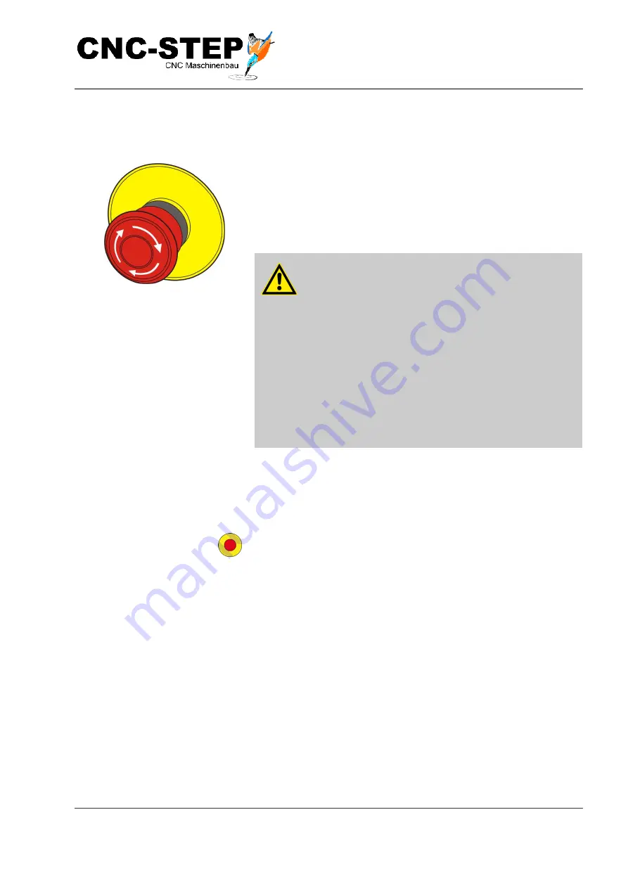
Emergency Stop Switch
Fig. 1: Emergency Stop Switch
By pressing the emergency stop button an emergency stop is
triggered and the drive motors are physically disconnected pre-
venting any movement.
After the emergency stop button has been pressed it must be un-
locked by twisting so that restarting is possible.
WARNING!
Danger to life through uncontrolled restart!
Uncontrolled restart can cause serious personal
injury or death.
- Before restart ensure that the cause for the
emergency stop has been eliminated, that all
safety devices have been reassembled and are
functional.
- Only unlock the emergency stop button if there is
no further danger
Location of the Emergency
Switches
Fig 2 Shows the location of the Emergency Stop Switches
This symbol indicates an Emergency Stop Switch


