background image

9.1

0

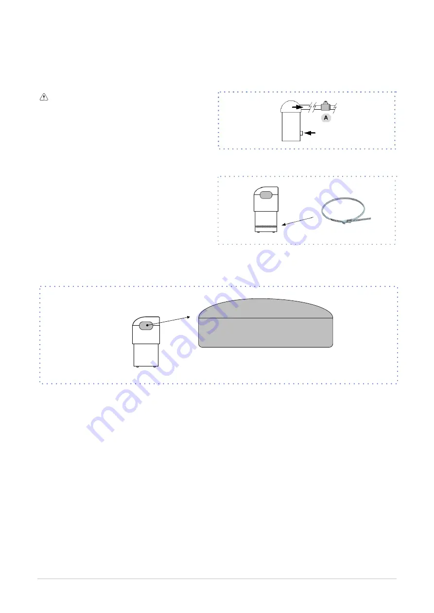
 Compressor supply line shut-off valve

9.1

1


C

rankcase heather

Do not remove the seal
Remove only if authorized by the manufacturer.
Please contact the maker for informations.

Check:

 closure

 Operation

9.1

2

 Copeland scroll compressor

Compressor may stop Pumping With Motor Running

Turn Off And Wait Until Cool

May need More Than 1 Hour To Reset

Advanced Scroll Temperature Protection

48

Summary of Contents for MSE-XSC3 100.4

Page 1: ...MSE XSC3 90 4 160 4 Installation and operating manual...

Page 2: ...he installation and maintenance cost for the life cycle of the system The purpose of this manual is to provide you with information that is useful from reception of the equipment through installation...

Page 3: ...Index of contents 1 4 2 6 3 8 4 10 5 14 6 18 7 26 8 35 9 47 10 52 11 53 12 54 57 3...

Page 4: ...cause damages to things and injuries people 1 4 Intended use Use the unit only for cooling heating water or a water and glycol mix keep to the limits foreseen in the technical schedule and in this man...

Page 5: ...thorized by the manufacturer The installer must train the user particularly on Start up shutdown Set points change Standby mode Maintenance What to do what not to do in case of breakdown 1 12 Unit ind...

Page 6: ...o supplier and the carrier Any disputes must be made within 8 days from the date of the delivery Complaints after this period are invalid 2 1 Storage Observe external packaging instructions 2 2 Handli...

Page 7: ...ful not to damage the unit Keep packing material out of children s reach it may be dangerous Recycle and dispose of the packaging material in conformity with local regulations A A Supports for handlin...

Page 8: ...wing criteria Customerapproval safe accessible position technical spaces requested by the unit max distance allowed by the electrical connections max distance allowed by the refrigerating pipes instal...

Page 9: ...supply and or failure from failed system clearing to clean system 4 2 Risk of freezing If the unit or the relative water connections are subject to temperatures close to 0 C mix water with glycol or s...

Page 10: ...Unit with VARIFLOW 6 7 12 8 11 9 10 6 7 12 8 11 9 10 18 19 13 14 15 16 17 1 3 5 1 3 5 19 2 2 2 1 exchanger 11 drain 2 Anti ice electric heater 12 Flow Switch 3 water temperature probe 13 System load s...

Page 11: ...lences Electrically connect the fl w switch at the inlet arranged on the XC terminal block The fl w switch must be set to the minimum reachable fl w rate A A A 5 x B A A minimum distance 4 10 Operatio...

Page 12: ...the rejected heating capacity cooling capacity compressor power input The recovery exchanger must be always maintained full of water The lack of water amplifies the noise generated by the operation W...

Page 13: ...check the safety device operation write on the serial label number the amount of total refrigerant issue the Declaration of conformity inform the user of the need to carry out regular checks 5 2 Vibra...

Page 14: ...capacity Provide for slopes 1 100 in the horizontal sections When the outdoor unit is positioned higher than the indoor unit provide siphons every 4 m in the vertical sections It is advisable to inse...

Page 15: ...refrigerant charge for equivalent lengths greater than 5 metres Diameter of the Refrigerant line tubing equal to that of the inlet outlet of the unit The final charge is to be the sum of the charge of...

Page 16: ...ge group Open the tap of the liquid line Open the taps of the gauge group and let liquid state refrigerant enter using an appropriate pump Once charging is complete open the gas tap so that the unit i...

Page 17: ...ad ampere absorbed current at maximum admitted conditions F L I full load input full load power input at max admissible condition Electrical wiringdiagram Nr 6 2 Connections 1 Refer to the unit electr...

Page 18: ...cables if vacated may be subject to tearing Respect the minimum distance from the ground to allow the entry of the power line The cable must not touch the compressor and the refrigerant piping they re...

Page 19: ...Connections performed by the Customer 19...

Page 20: ...150 1x150 1x150 1x240 Max cable section Cu mm 1x185 1x185 1x240 1x240 1x240 1x240 Min bar Cu section mm Max bar Cu width mm 32 32 32 32 32 40 Tightening torque Nm 20 20 20 20 20 20 6 6 Remote ON OFF D...

Page 21: ...ct Modify board setting 5 select Local area connection LAN 6 select Internet protocol version 4 TPC IPV4 and enter Property 7 set the IP address 192 168 1 100 8 set Subnet mask as 255 255 255 0 9 conf...

Page 22: ...t A User interface 2 Distance up to 700 mt B B1 KNX bus max 350 mt twisted pair with shield 0 8 mm EIB KNX cable marking recommende C PSX Mains power supply unit pwer supply unit N125 11 5WG1 125 1AB1...

Page 23: ...serial line must be set up using the In Out bus system Other types of networks are not allowed such as Star or Ring networks The difference in potential between the earth of the two RS485 devices tha...

Page 24: ...ed flashing software error red flashing communicating not possible fixed hardware error communication down 6 11 BACnet IP Option LED BSP communication with AP1 module LED BUS communication with BACnet...

Page 25: ...power wait at least 5 minutes before accessing to the electrical panel or any other electrical component Before accessing check with a multimeter that there are no residual stresses 7 2 Preliminary c...

Page 26: ...uit 1 Before realizing the unit connection make sure that the hydraulic system has been cleaned up and the cleaning water has been drained 2 Check that the water circuit has been filled and p essurize...

Page 27: ...atedintheDIAGRAMOFSUGGESTEDWATERCONNECTIONS 7 10 Voltages Check that the air and water temperatures are within in the operating limits Start up the unit With unit operating in stable conditions check...

Page 28: ...vailable to meet the thermal need If only P0002 EnDemandLimit 0 Path Main Menu Unit parameters Demand limit Step Display Action Menu Variable Keys Notes 1 Press 3 sec 2 Password Set Password 3 Press 4...

Page 29: ...ect Local connections Path Main Menu Unit parameters TExt Correction config Parameters Short description description P0606 CSptLow setpoint temperature value when the air temperature value is AirAtSpt...

Page 30: ...eset Select Parameter 7 Set 8 Confirm 9 Press 3 sec 10 Select Local connections Path Main Menu Unit parameters Water reset Parameters Short description description P0616 MaxCWRC Maximum correction to...

Page 31: ...IB KNX cable Possible connections Tree star in out bus mixed It is not possible to use a ring connection No end of line resistor or terminator required There must be suitable arresters to protect the...

Page 32: ...l H2O temperature control MODE C The master manages the single cooling The master optimizes individual refrigerant circuits Active pumps only with active compressors P0658 2 P0657 0 C setpoint1 setpoi...

Page 33: ...he refrigerating circuit compressor discharge liquid intake The measurements must be kept and made available during maintenance interventions 7 18 2014 68 UE PED directive DIRECTIVE 2014 68 UE PED giv...

Page 34: ...utility side D T OutH2OUtilitySide Water outlet temperature utility side E ActualState On off eco pmp On F ActualMode Cool water cooling Heat HEATING 2 Installed compressors 1 0 Compressors ON exampl...

Page 35: ...nfirm 5 Exit 8 6 Modify setpoint Step Display Action Menu Variable Keys Notes 1 Press 2 Main menu Select Unit parameters 3 Unit parameters Confirm Set Point 4 Select Set Point 5 Set Set Point 6 Confir...

Page 36: ...ct Value 8 Set On Eco 9 Confirm 10 Exit Enable Scheduler Step Display Action Menu Variable Keys Notes 1 Press 3 sec 2 Password Set Password 3 Press 4 Main menu Select Unit Parameters 5 Select Option c...

Page 37: ...83 User side Inverter Command 84 User side Inverter Signal 85 User side Inverter Reset 86 Pump On for Anti freeze 87 Anti freeze Heaters User side 88 User side Flow Request 89 LimitFlow Heating 90 Li...

Page 38: ...Compressor 2 1 Protection 1184 Source Fan 1 1 Protection 2180 High Pressure 1 2 2181 Compressor 1 2 Protection 2183 Compressor 2 2 Protection 2184 Source Fan 1 2 Protection Nr ANALOGIC INPUT 201 Deman...

Page 39: ...Injection 1 1 1302 Source Pump 1 1 Command 1303 Compressor 1 1 Command 1304 Compressor 2 1 Command 1305 Liquid Injection 1 1 1306 Liquid Injection 2 1 1307 RecValve Battery 1 1 1308 RecValve Chiller...

Page 40: ...ample eE0001 Phase monitor Fault active alarm EE0003 Pum 1 faulty Ok resetted alarm Display of alarm step 1 3 Reset allarm step 4 10 Step Display Action Menu Variable Keys Notes 1 Press 2 Alarm list d...

Page 41: ...ault HW ee0030 DemandLimit Demand limit fault HW ee0031 WaterReset Water reset fault HW ee0032 External Humidity probe Error Relative humidity probe fault HW ee0033 T Quadro Ele Electrical panel tempe...

Page 42: ...e probe fault HW Circuit 1 ee1025 T Source 1 Source 1 temperature probe fault HW Circuit 1 ee1026 T Source 2 Source 2 temperature probe fault HW Circuit 1 ee1027 T Suction Gas Suction temperature prob...

Page 43: ...tection Source side pump 1 overload protection Source 2 EE2014 Source Pump 2 protection Source side pump 2 overload protection Source 2 EE2015 Source Pump 3 protection Source side pump 3 overload prot...

Page 44: ...connection problem HW Circuit 2 ee2071 Source ECV 1 1 Source side ECV 1 connection problem HW Circuit 2 ee2072 Source ECV 2 1 Source side ECV 2 connection problem HW Circuit 2 REFRIGERANT CIRCUIT ALA...

Page 45: ...defrost Circuit 2 ff2049 DFRTimeMax Defrost Time Circuit 2 HYDRAULIC CIRCUIT ALARMS Num Name Description Category iI0002 Water pressure User side low water pressure GP Ut iI0006 Flow switch utility si...

Page 46: ...use service necessary intervention frequency months 1 6 12 1 presence corrosion X 2 panel fixing X 3 4 5 water filter cleaning X 6 water quality ph weight of glycol X 7 check the exchanger efficiency...

Page 47: ...changer It is very important for the exchanger to be able to provide the maximum thermal exchange therefore it is essential for the inner surfaces to be clean of dirt and incrustations Periodically ch...

Page 48: ...ve only if authorized by the manufacturer Please contact the maker for informations Check closure Operation 9 12 Copeland scroll compressor Compressor may stop Pumping With Motor Running Turn Off And...

Page 49: ...liquid contained in the system should not be discharged freely as it is a pollutant It must be collected and reused Before starting a washing the plant Example emptying pump It s recommended that the...

Page 50: ...9 15 Compressor replacement 50...

Page 51: ...9 16 Exchanger replacement 51...

Page 52: ...slation in question are marked with the symbol on the side With the aim of protecting the environment all of our units are produced in compliance with Directive EC on waste electrical and electronic e...

Page 53: ...that all of the panels are correctly closed and fixed If there is a fire the temperature of the refrigerant could reach values that in crease the pressure to beyond the safety valve with the conseque...

Page 54: ...W 106 5 117 4 127 0 144 6 165 8 187 0 F L I Total A 180 6 191 9 208 7 237 5 266 5 295 5 M I C Value 3 A 431 0 442 3 459 1 487 9 586 4 615 4 M I C with soft start accessory 3 A 293 2 304 5 321 3 350 1...

Page 55: ...1 004 1 020 SIZE 90 4 100 4 110 4 120 4 140 4 160 4 Qmin l s 6 7 7 4 8 0 9 3 10 1 11 5 Qmax l s 18 3 20 0 21 8 25 1 27 5 31 2 INTERNAL EXCHANGER EVAPORATOR m2 K W F1 FK1 0 44 x 10 4 1 0 1 0 0 88 x 10...

Page 56: ...internal exchanger outlet water temperature 1 Standard unit operating range 2 Unit operating range in B Low water temperature configuration 40 ethylene glycol When choosing the remote condenser take i...

Page 57: ...line circuit 1 12 Gas line circuit 1 13 Gas line crcuit 2 14 Liquid line circuit 2 SIZE 90 4 100 4 110 4 120 4 140 4 160 4 OD internal exchanger mm 114 3 114 3 114 3 114 3 114 3 114 3 OD1 partial rec...

Page 58: ...ltre BL Italy Tel 39 0439 3131 Fax 39 0439 313300 info clivet it www clivet com FOR OVER 25 YEARS WE HAVE BEEN OFFERING SOLUTIONS TO ENSURE SUSTAINABLE COMFORT AND THE WELL BEING OF PEOPLE AND THE ENV...

Reviews: