background image


 pag 

31 

DUCTING 

Check the fixing screws and the operation of the anti-vibration devices in order to prevent the transmission of vibrations in the 
room. 

ELECTRIC FANS  

Make sure that the fans and the relative protection grids are well fixed. 
Check, if possible, the unbalances of the electro-fan evident by noise and anomalous vibrations. Verify that the terminal 
protection covers are closed and the cable holders are properly positioned. 


STEAM HUMIDIFIER AND IMMERSED ELECTRODES 

The humidifier and the cylinder contain live electrical components and hot surfaces. All maintenance operations must be 
performed by qualified, experienced personnel who have been trained on possible hazards.  
During operation, the steam production cylinder reaches high temperatures! 
Maintenance must be performed after the cylinder has cooled. Use protective gloves. 
The cylinder must be replaced periodically. This operation is necessary when lime incrustations build up on the inside such 
that sufficient current passage does not occur. How frequently this needs to be done depends on the water supply. The harder 
the water, the more often the cylinder will need to be replaced. The water supply must not be softened. This causes corrosion 
of the electrodes, foaming and possible abnormal operation. After prolonged use or use with very hard water, the solid 
deposits on the electrodes may increase in size until they adhere to the inner wall of the cylinder. With especially conductive 
deposits, the plastic may heat so much that it melts, resulting in water leakage.  
In case of leaks, power off the unit before touching the cylinder, because electrical current may be flowing through the water. 

PERIODIC CHECKS OF CYLINDER 

fortnightly 

after not more than 300 hours of service 

check of operation, general condition, lack of 
leaks 

quarterly 

after not more than 1000 hours of service 

check of operation, general condition, lack of 
leaks, any replacement required 

yearly 

after not more than 2500 hours of service 
(disposable cylinders) 

replacement of cylinder 

5 years 

after not more than 10000 hours of service (for 
inspectable cylinders) 

replacement of cylinder 

YEARLY CHECK OF COMPONENTS


Do not use detergents or solvents to clean plastic components. 
To remove incrustations, wash with a 20% solution of vinegar or acetic acid, and then rinse with water.  

filling solenoid valve 

disconnect the electrical power supply, remove the valve, and clean 
the filter 

drainage solenoid valve 

disconnect the electrical power supply, remove the bobbin, 
disassemble the valve body, remove any impurities and rinse 

supply tub, pipes 

check that they are free and without impurities 


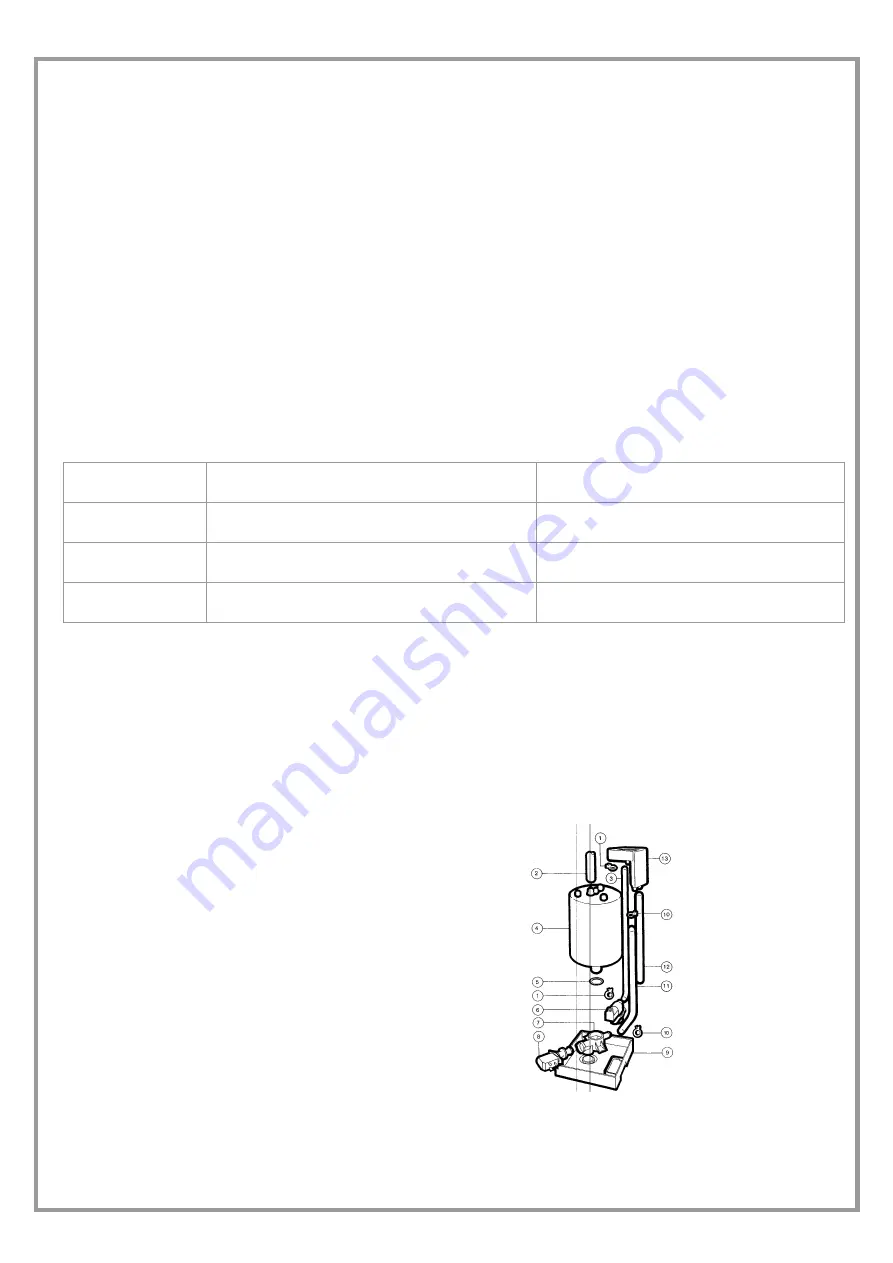
REPLACEMENT OF CYLINDER


To remove the cylinder: 

  Completely drain the water. 

  Cut power to the humidifier using the disconnecting switch of the unit. 

  Remove the steam tube from the cylinder. 

  Detach the electrical connections of the electrodes and remove the 

plugs from the high-level electrodes. 

  Unscrew the ring nut to remove the nozzle and the filter (when the 

filter is outside the cylinder) 

  Lift the cylinder to extract it 


Before putting it back in place: 

  The filter body does not need to be replaced. Wash it with water and 

place it on the new cylinder, using the new gasket that comes with it. 

  Check the gasket for the seal between the cylinder and the drain group. 

  Put the cylinder back in place by repeating the operations in reverse order


1 -  pipe fastening spring
2 -  steam pipe 
3 -  filling pipe  
4 -  steam cylinder 
5 -  O-ring seal 
6 -  filling valve 
7 -  valve support 
8 -  discharge valve 
9 -  bottom tub 
10 -pipe fastening spring
11 -filling pipe  
12 - overflow pipe 


ELECTRICAL HEATING ELEMENTS 

The convector finned heating elements need to be checked regularly to ensure that they are clean and properly fastened to the 
support. 
 

Summary of Contents for CPAN-U-17

Page 1: ...CPAN U 17 21 25 31 41 51 ELFOFRESH LARGE Make up unit full fresh air Installation and Use Manual M25E40P5 11 22 04 14...

Page 2: ......

Page 3: ...MAINS 15 FUNCTIONAL CONNECTIONS 15 SYSTEM COMPOSITION 16 S T A R T U P 1 7 PRELIMINARY CHECKS 17 AERAULIC SYSTEM 17 REFRIGERANT SYSTEM 17 WATER SYSTEM 17 ELECTRICAL SYSTEM 17 VERIFy tensions absorpti...

Page 4: ...This provides unique identification of the machine It makes it possible to trace the specific features of the unit and to identify the components installed in it Without this number it is not possible...

Page 5: ...pressed SUMMER WINTER MODE CHANGE Key hold pressed The key is not operative if the unit is set for the automatic operating mode under such conditions the AUTO indication is displayed SOLO FAN Holding...

Page 6: ...e instructions given in this manual will cause the warranty to lapse INTENDED USE The unit must only be used for the specific purpose it was designed The unit is designed for civil air conditioning wi...

Page 7: ...L RISKS A smell of burning smoke or other indications of serious irregularity could signal the onset of situations liable to cause damage to persons or property or to the unit itself Isolate the unit...

Page 8: ...0 in weight CEE No Non applicable for mixtures Commercial name 03 Hazard identification Hazard identification Liquefied gas Vapours are heavier than air and can cause choking by reducing the oxygen av...

Page 9: ...alve if supplied is correctly assembled Verify that the cap if supplied is well assembled and that there is adequate ventilation Verify that the norms in force are respected 15 Information on the norm...

Page 10: ...es which activate the safety valves HANDLING The operation of handling the unit must be carried out respecting the instructions of the safety norms in force Legislative Decree 626 94 and following mod...

Page 11: ...s must be doubled POSITIONING 1 The units are designed for INDOOR installations performed in fixed positions and in areas accessible only to qualified and authorized personnel 2 SAFETY VALVE only if p...

Page 12: ...IONS SUPPORTS The weight of the hydraulic connections must be supported in the exterior of the unit so as not to stress the connections of user devices exchangers coils humidifiers etc ANTI VIBRATION...

Page 13: ...cs pressure inclusive between 0 1 and 0 8 Mpa 1 8bar temperature inclusive between 1 and 40 C Do not use softened water it may cause corrosion of the electrodes and foaming resulting in malfunctions f...

Page 14: ...ak off the short circuit power whose value should be determined according to the plant features The section of supply cables and protection cable must be seized according to the characteristics of the...

Page 15: ...cess is reserved to authorized assistance centres in order to avoid unauthorized modifications ON OFF FROM REMOTE CONTROL Generally the unit is delivered with bridged terminals if the control is not u...

Page 16: ...ions available on the machine keyboard SERIAL CONVERTER TTL RS485 OPTIONAL code PE6B0020 The supervision services are available with standard modbus protocol Plugged in in the main module on the elect...

Page 17: ...er Open the cocks of the refrigerator circuit if there are any Using the unit manometers if present or service manometers verify that the refrigerating circuit is in pressure Make sure that all the se...

Page 18: ...condensation pressure increases The phase optional monitor which controls the phase sequence can be installed later REMOTE INPUT CONFIGURATIONS Check used remote inputs are activated ON OFF etc as giv...

Page 19: ...tilation EXTERNAL temperature 10 C 35 C OFF OFF ON AMBIENT temperature 16 C 30 C OFF OFF ON OUTLET temperature OPERATING MODES SUMMER WINTER MODE MODE CHANGE MANUAL The choice between the HEATING or t...

Page 20: ...acing them of 1 C respect the manual set COOLING 24 C HEATING 22 C AUTOMATIC AMBIENT SET POINT The set point can also be adjusted AUTOMATICALLY to the external temperature variations the variation cur...

Page 21: ...t alarms are reset holding the buttons ECO and Clean pressed KEY LOCK All button functions can be locked by holding the buttons Clean and On Off pressed The lock is signalled by the characters wheneve...

Page 22: ...by the ALARM CODE blinking and by the machine time it they occurred The cumulative lock relay activates simultaneously with the alarm code displaying Some alarms typically PRE ALARMS do not activate...

Page 23: ...ess Dehumidification signalling with reduced flow rate E33 Recovery compressor lockout for low enthalpy ambient air temperature heat mode Automatic Recovery compressor lockout and ventilation lockout...

Page 24: ...e key ON OFF pressed With unit off the indication OFF is displayed even if the unit has been switched off by a digital input or supervisor COOLING HEATING SELECTION To select the unit operating mode h...

Page 25: ...11 Setpoint compensation outside temperature 4 Text4 30 C 12 Setpoint compensation value 0 set 00 19 C 13 Setpoint compensation value 1 set 01 21 C 14 Setpoint compensation value 2 set 02 23 C 15 Setp...

Page 26: ...ompressor operating mode 1 heat pump 0 1 010 Active dehumidification status 0 1 011 Free Cooling status 0 1 012 Free Heating status 0 1 013 Vfan control variable 014 Supply Fan control signal 015 Supp...

Page 27: ...homologation day 044 Modulation time of resi stance water control valve opening count sec 045 Correction time of resi stance water control valve opening count sec 046 On off status of electrostatic f...

Page 28: ...Verify that the aluminum fins are not bent or damaged In the event of damages contact the authorized assistance center and get the battery ironed out in order to restore the initial condition for an...

Page 29: ...ion 3 Fill the spray pump with the prepared solution 4 Position the filter to be washed on a support so you can work comfortably Spray the detergent on the blades of the electrostatic filter 5 Also sp...

Page 30: ...y fine grain steel wool Because of the high voltage that powers them the ionization wires are subject to wear Yearly replacement will prevent unexpected breakage If breakage occurs 1 Remove all pieces...

Page 31: ...general condition lack of leaks quarterly after not more than 1000 hours of service check of operation general condition lack of leaks any replacement required yearly after not more than 2500 hours of...

Page 32: ...th a corrosive atmosphere 97 23 CE PED DIRECTIVE PUT AT REST If a long period of inactivity is foreseen for example the winter for the cooling unit the following is recommended to turn the power off i...

Page 33: ...20 8 35 71 25 8 44 22 30 8 51 59 35 8 58 09 40 8 63 92 1 0 37 03 6 0 4 10 11 0 13 40 16 0 26 01 21 0 36 08 26 0 44 53 31 0 51 86 36 0 58 34 41 0 64 14 1 2 34 84 6 2 3 24 11 2 13 97 16 2 26 46 21 2 36...

Page 34: ...eds calibrating insufficient refrigerant charge FAN PROTECTION 1 Identify the part on the wiring diagram 2 fan mechanically jammed bearings drive belt if present 3 Loose electric contacts terminals le...

Page 35: ...ored in special containers When recovering the substances present in the unit all measures must be taken to avoid damaging persons and things and polluting the surrounding area Awaiting dismantling an...

Page 36: ...00 180 270 340 AIR HANDLING SECTION FANS EXHAUST Type of fans 4 CFG Number of fans 1 Standard air flow l s 300 360 440 550 640 860 Installed unit power kW 0 3 0 3 0 4 0 4 0 6 0 6 Max outside static pr...

Page 37: ...ET BULB TO OUTDOOR AIR TEMPERATURE HANDLING COIL INLET C DB DRY BULB 1 THE DASHED AREA REFERS TO THE FIELD OF UNITS OPERATION STANDARD 2 OPERATION FIELD EXTENSION WITH PREHEATING HEATERS SOUND LEVELS...

Page 38: ...ER OUTLET ADDITIONAL COIL 3 4 15 WATER INLET ADDITIONAL COIL 3 4 16 HUMIDIFIER INLET WATER 1 2 GAS 17 CONDENSATE DISCHARGE 18 AUXILIARY ELECTRIC HEATERS OPTIONAL 19 EXHAUST AIR FILTER G4 OPTIONAL 20 B...

Page 39: ...T ADDITIONAL COIL 3 4 15 WATER INLET ADDITIONAL COIL 3 4 16 HUMIDIFIER INLET WATER 1 2 GAS 17 CONDENSATE DISCHARGE 18 AUXILIARY ELECTRIC HEATERS OPTIONAL 19 EXHAUST AIR FILTER G4 OPTIONAL 20 BRACKETS...

Page 40: ...R OUTLET ADDITIONAL COIL 3 4 15 WATER INLET ADDITIONAL COIL 3 4 16 HUMIDIFIER INLET WATER 1 2 GAS 17 CONDENSATE DISCHARGE 18 AUXILIARY ELECTRIC HEATERS OPTIONAL 19 EXHAUST AIR FILTER G4 OPTIONAL 20 BR...

Page 41: ...T ADDITIONAL COIL 3 4 15 WATER INLET ADDITIONAL COIL 3 4 16 HUMIDIFIER INLET WATER 1 2 GAS 17 CONDENSATE DISCHARGE 18 AUXILIARY ELECTRIC HEATERS OPTIONAL 19 EXHAUST AIR FILTER G4 OPTIONAL 20 BRACKETS...

Page 42: ...pag 42...

Page 43: ...pag 43...

Page 44: ...93 8606248 Fax 34 93 8855392 info clivetcomercial com CLIVET ESPA A S A U Service and Maintenance Division Calle Real de Burgos N 12 28860 Paracuellos del Jarama Madrid Espa a Tel 34 91 6658280 Fax 34...

Reviews: