background image

ClientPOS


PT6300 User Manual 

Version: 2.0 

36 | 95 


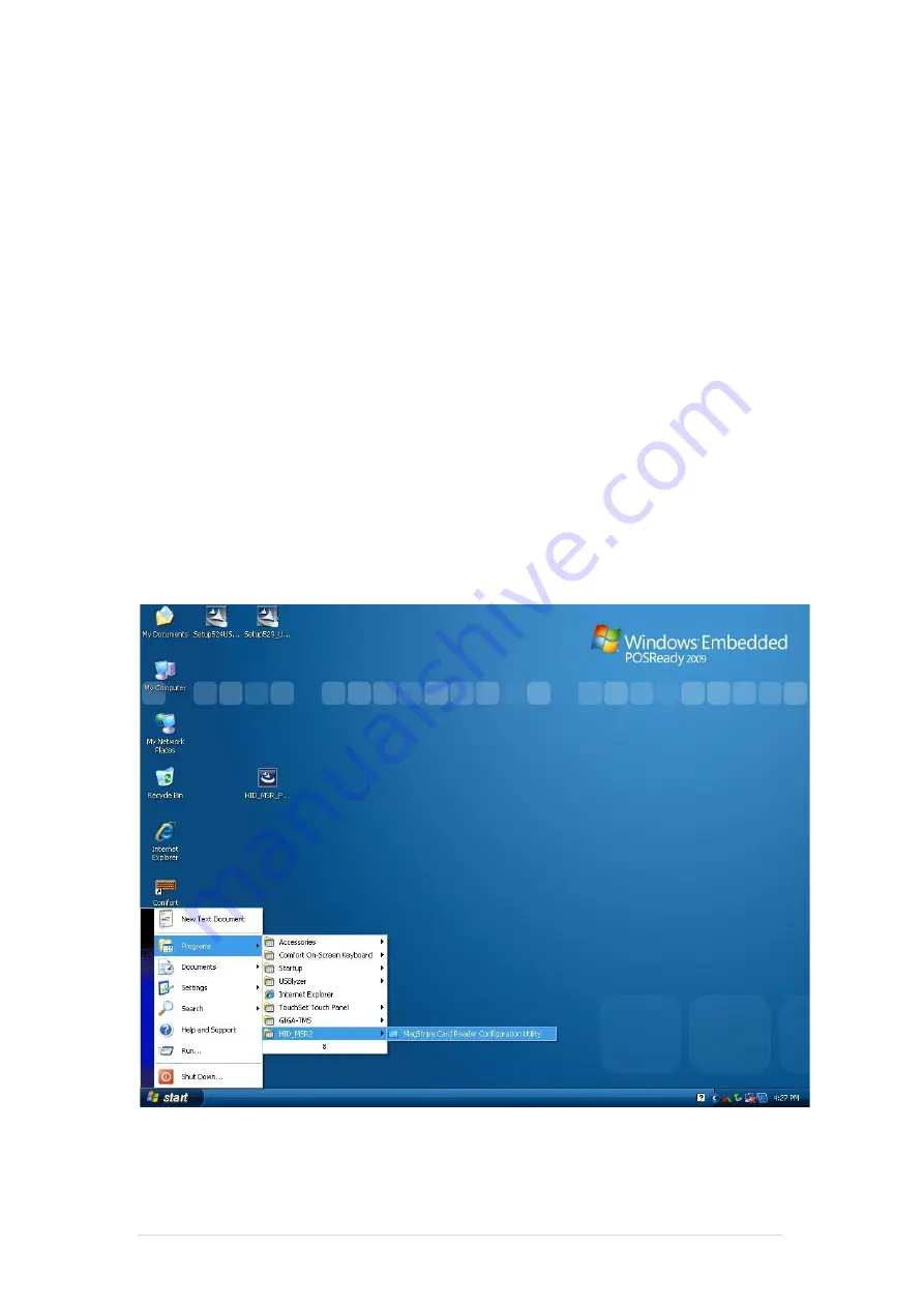
6-2  MagStripe Card Reader Configuration Utility   


The MagStripe Card Reader Configuration Utility is used to set up the output format of HID 

MSR   


Installation 


Below steps guide you how to install the Utility program.   


Insert the setup CD   


Run the 

HID_MSR_PSW00003_V2_0_0.exe 

setup file that is located in the Software 

folder of CD.   


Follow the wizard to complete the installation.   


Launching Program 


Below steps guide you how to load the 

Utility 

program.   


From 

Start

/

Programs

, click 

HID_MSR2 

folder   


Click 

MagStripe Card Reader Configuration Utility 

to launch the program.   


Summary of Contents for PT6300

Page 1: ...1 95 PT6300 User Manual Version 2 0 P N Cover page ...

Page 2: ...s written permission of the publisher All products and trade names described within are mentioned for identification purpose only No affiliation with or endorsement of the manufacturer is made or implied Product names and brands appearing in this manual are registered trademarks of their respective companies The information published herein has been checked for accuracy as of publishing time No re...

Page 3: ...ng this could cause fire or electrical shock 9 If one of the following situations arises get the equipment checked by a service personnel a The power cord or plug is damaged b Liquid has penetrated into the equipment c The equipment has been exposed to moisture d The equipment does not work well or you can not get it work according to user manual e The equipment has dropped and damaged 10 Do not l...

Page 4: ...al VFD 5 7 Wi Fi 5 8 8 2nd Display 5 9 1D 2D i Button with RFID module 6 Device Driver Installation 6 1 Resistive Type Touch Panel and P Cup 6 2 MagStripe Card Reader Configuration Utility 6 3 Fingerprint Reader 6 4 RFID 6 5 Internal VFD 6 6 i Button Reader Configuration Utility 6 7 Installation and Testing of Smart Card Reader 6 8 Wi Fi 7 BIOS Utility Setup 7 1 Advanced 7 2 Chipset 7 3 Boot 7 4 S...

Page 5: ...ClientPOS PT6300 User Manual Version 2 0 5 95 7 5 Save Exit 8 LCD Surface Cleaning P93 P94 ...

Page 6: ... List 1 1 Standard Accessories a b a System with stand b Power Adapter c Power Cord d Driver Bank e Screw x2 f Cable Cover c d e f 1 2 Optional Accessories a b a Single MSR b 3 IN 1 MSR c Screw x2 c Packing List 1 ...

Page 7: ...w Item 1 Mic 2 Line Out 3 RJ11 Cash Drawer 4 RJ45 LAN 5 USB 2 0 X4 6 COM1 7 VGA 8 COM2 9 RJ45 COM 3 external 10 PS2 K B 11 19V DC Input 12 Parallel port Option 13 Power Button 14 MSR Smart Card i Button Fingerprint RFID Option 15 VFD Option 16 HDD CFast CARD System View 2 ...

Page 8: ...t Mic in Network RJ45 10 100 1000 Base T USB 4 USB 2 0 Storage CFast type I 2 5 SATA HDD SSD BIOS AMI UEFI BIOS Power DC 19V 180W Adaptor Thermal Solution Heat sink Fan X3 Dimension 368 W x 264 2 H x 285 D mm Operating Temperature 0 C 35 C Storage Temperature 20 C 60 C Storage Humidity 20 80 non condensing Display LCD Panel Size 15 inch TFT Active Matrix Display Resolution 1024 768 Pixels Brightne...

Page 9: ...ClientPOS PT6300 User Manual Version 2 0 9 95 2 3 Internal Layout ...

Page 10: ... second Resistance state should the same 5 1 Linearity should the same 5 2 Insulation resistance should the same 5 3 2 4 2 Hand Writing test Write one hundred thousand times of 40mm straight line to and fro counts as twice with and engineering plastic stylus in AA area The measurement items must satisfy the under mentioned items Writing force shall be 250g and writing speed 3 000 times per hour Re...

Page 11: ...rt DATA2 17 SLIN Printer Select Input 5 PD3 Parallel Port DATA3 18 GND Ground 6 PD4 Parallel Port DATA4 19 GND Ground 7 PD5 Parallel Port DATA5 20 GND Ground 8 PD6 Parallel Port DATA6 9 PD7 Parallel Port DATA7 10 ACK Printer Acknowledge 11 BUSY Printer Busy 12 PE Printer Paper End 13 SLCT Printer Select 3 Lin out J3 Pin NO Pin Name Description 1 GND Ground 2 GND Ground 3 Line OUT R Line out 4 Line...

Page 12: ...3v 16 GND Ground 3 GND Ground 17 NC NC 4 NC NC 18 NC NC 5 DATA 0 LVDS Output DATA0 19 GND Ground 6 DATA 0 LVDS Output DATA0 20 NC NC 7 GND Ground 8 DATA 1 LVDS Output DATA1 9 DATA 1 LVDS Output DATA1 10 GND Ground 11 DATA 2 LVDS Output DATA2 12 DATA 2 LVDS Output DATA2 13 GND Ground 14 CLK LVDS CLK 8 Inverter CN14 Pin NO Pin Name Description 1 VCC 12V 2 GND Ground 3 NC NC 4 BKL_CTL Back Light Brig...

Page 13: ...t Blue Video 11 In Monitor ID 0 4 In Monitor ID 2 12 In Monitor ID 1 5 TTL Ground Monitor Self Test 13 Out Horizontal Sync 6 Red Analogue Ground 14 Out Vertical Sync 7 Green Analogue Ground 15 In Monitor ID 3 8 Blue Analogue Ground 3 USB port Pin Signal Name Wire Colour Comment 1 VCC Red Cable Power 2 Data White Data Transfer 3 Data Green Data Transfer 4 Ground Black Cable Ground Shell Shield Drai...

Page 14: ...ive 4 Blue Not Used 5 White Blue Not Used 6 Green Receive 7 White Brown Not Used 8 Brown Not Used 6 RJ11 port for Cash Drawer Pin Signal Name Direction 1 Frame GND 2 Drawer Kick out drive signal 1 Output 3 N C 4 12V 5 N C 6 Signal GND 7 DC Jack Pin Signal Name 1 DC IN 19V 2 Ground Example DOS COMMAND for Cash Drawer 1 Create the file TEST TXT 2 Input below contents in TEST TXT CONTEXT 000 0 MODE C...

Page 15: ... Assembly Disassembly 5 1 HDD 1 Unfasten the HDD cover screw 2 2 Pull out the HDD bracket 3 Fasten the screw 4 4 Place the HDD bracket back to the module 5 2 CFast Card 1 Please notice the unnotched CFast Card This side up UP System Assembly Disassembly 5 ...

Page 16: ...ClientPOS PT6300 User Manual Version 2 0 16 95 2 Before Installing CFast Card 3 After Installing CFast Card ...

Page 17: ... 2 0 17 95 5 3 MSR 1 Open the MSR cover 2 Single MSR or 3 in 1 MSR 3 Screw 2 M3x10L 4 Fasten the screw 5 4 cable cover Assemble the cable cover from bottom and make sure the two latches are on the right position Then fasten 2 screws M3 5L ...

Page 18: ...ClientPOS PT6300 User Manual Version 2 0 18 95 5 5 15 2nd Display 1 Remove the plastic pole cover from the stand 2 Install the pole into the socket in clockwise direction ...

Page 19: ...ct the COM port DC cable as shown in figure Please refer to page 89 to set the COM port pin9 with 12V DC output 5 Connect the VGA cable as shown in figure 6 Connect the audio cable as shown in figure 7 Assemble the cable cover from bottom and make sure the two latches are on the right position and fasten the two screws M3 5L 2 3 1 ...

Page 20: ... the opening of stand front cover and cable clip at the bottom and route the cables into the tube of pole 9 Reeve the cables out of the tube 10 Mount the VESA bracket on the pole and route cables out of the tube of VESA bracket Fasten the thumb screw to fix the VESA bracket ...

Page 21: ...ser Manual Version 2 0 21 95 11 Connect the DC power cable as shown in figure 12 Connect the VGA cable as shown in figure 13 Connect the Audio cable as shown in figure 14 Put the cable cover on the hinge of VESA bracket ...

Page 22: ...ar cover by TAPPING SCREW R H M3 8L x 2pcs As Fig 5 Torque 2Kgf 6 The VFD CABLE must be around to capacitor H below so as not to interfere HINGE action As Fig 6 Item P N and Component 1 20D990002 000B DISPLAY MODULE VFD 1 2 68D350235 000B COVER FOR VFD 1 3 78D300021 000B HOLDER FOR VFD 1 4 26D100005 000B HINGE ASSY FOR VFD 1 5 64D426051 000T SCREW TAPPING P H 2 6φ 5 8 6 64D430088 000T SCREW TAPPIN...

Page 23: ...al to the right of the left snap as the red frame as shown in the figure below 2 After fastening the Wi Fi Module to the Rubber Part No 78D200655 000T fix this on the VFD cover The left side of Wi Fi module should align the interior cover as the position of the red line The right side of Wi Fi module should align another side as the red circle ...

Page 24: ...ure below 4 Fasten antenna cable connector to Wi Fi module terminal Then fasten antenna cable to the cover by adhesive tapes 5 Fasten the VFD cover to the rear lid Push the snap of the top VFD cover into the slot of rear lid and fasten the bottom cover with 2 screws Part No 64D430088 000T Then connect Wi Fi MSR cable Part No 35D510522 000B to Wi Fi module Alternative of WiFi or Internal VFD ...

Page 25: ...ClientPOS PT6300 User Manual Version 2 0 25 95 5 8 8 2nd Display 1 Remove the plastic pole cover from the stand 2 Install the pole into the socket in clockwise direction ...

Page 26: ...ClientPOS PT6300 User Manual Version 2 0 26 95 3 Connect VGA cable and DC power cable 4 Fasten the four screws M4 8L to joint the VESA bracket and the rear cover 5 Reeve the cables out of the tube ...

Page 27: ... pole and route cables out of the tube of VESA bracket Fasten the thumb screw to fix the VESA bracket 7 Reeve the cables out from the bottom of pole 8 Route the cables through the opening of stand front cover and cable clip at the bottom and route the cables into the tube of pole ...

Page 28: ...DC power cable as shown in figure To setup COM port PIN9 with 12V DC output from BIOS setup please refer to page 89 Advanced Chipset Features COM port PIN9 setting 10 Connect the VGA cable as shown in figure 11 Put the cable cover on the hinge of VESA bracket 2 1 ...

Page 29: ...scanner with RFID module Connect the cable as shown in figure b For 1D barcode scanner with RFID module Connect the cable as shown in figure Before COM port cable connection please setup COM port PIN9 with 5V DC output from BIOS setup Please refer to page 89 Advanced Chipset Features COM port PIN9 setting 2 Fix the screws as shown in below figure 1 2 ...

Page 30: ...ClientPOS PT6300 User Manual Version 2 0 30 95 6 Device Driver Installation 6 1 Resistive Type Touch Panel and P CAP 1 Click Next 2 Click Next Device Driver Installation 6 ...

Page 31: ...ClientPOS PT6300 User Manual Version 2 0 31 95 3 Click Next 4 Select None Click Next 5 Click OK ...

Page 32: ...ClientPOS PT6300 User Manual Version 2 0 32 95 6 Select Support Multi Monitor System Click Next 7 Click Next ...

Page 33: ...ClientPOS PT6300 User Manual Version 2 0 33 95 8 Click Next 9 Click Next ...

Page 34: ...ClientPOS PT6300 User Manual Version 2 0 34 95 10 Select Create a eGalaxTouch Utility shortcut on desktop Click Next ...

Page 35: ...ClientPOS PT6300 User Manual Version 2 0 35 95 12 Would you do 4 point calibration now Click Yes 13 Do 4 points aligrment to match display 14 Calibration utility ...

Page 36: ...n Below steps guide you how to install the Utility program Insert the setup CD Run the HID_MSR_PSW00003_V2_0_0 exe setup file that is located in the Software folder of CD Follow the wizard to complete the installation Launching Program Below steps guide you how to load the Utility program From Start Programs click HID_MSR2 folder Click MagStripe Card Reader Configuration Utility to launch the prog...

Page 37: ...ogram For the settings there are Language The language defines the code positions of the keyboard Each language should use its own settings Wrong language selected will cause the wrong character displayed Prefix Suffix Defines the data string which you would like to append in front or end of the MSR data string Error Message Indicates which track number cause the error Delimiter Indicates the swip...

Page 38: ...are 4 kinds of prefix and suffix to be defined which are Package For the prefix string it is appended in the front of the whole MSR data For the suffix it is appended in the end of the whole MSR data In most case the suffix for package is always to be the Enter or Tab character The max data length of the prefix and suffix for the package can be up to 127 TK1 For the prefix string it is appended in...

Page 39: ...Track Data Filtering Shown below is the filter setting for track 1 This provides a fool proofing method in case of receiving unwanted or uncompleted track data These three filter settings are Enable If selected the data of specified track will be packaged in the MSR data string If the specified track data is not decoded it will leave blank in the MSR data string Required If selected which means th...

Page 40: ...to update the settings to connected HID MSR reader Save Settings To save the settings to a file click Save specify the file name and location to be saved Open Settings To load pre saved settings click Open specify the settings file and then click OK to load into program Restore MSR Reader Settings To load restore settings of connected MSR reader click Restore ES2 End sentinel for track ...

Page 41: ...41 95 6 3 Fingerprint Reader 1 Check Fingerprint reader be detected by Device manager 2 Select SDK folder ...

Page 42: ...ClientPOS PT6300 User Manual Version 2 0 42 95 3 Run Setup exe 4 Click Next ...

Page 43: ...ClientPOS PT6300 User Manual Version 2 0 43 95 5 Select I accept the terms in the license agreement and click Next 6 Click Next ...

Page 44: ...ClientPOS PT6300 User Manual Version 2 0 44 95 7 Click Next 8 Click Install ...

Page 45: ...ClientPOS PT6300 User Manual Version 2 0 45 95 9 Click Finish 10 Restart systems ...

Page 46: ...ClientPOS PT6300 User Manual Version 2 0 46 95 11 Check Fingerprint reader in Device Manager 12 Launch Fingerprint reader from start menu ...

Page 47: ...ClientPOS PT6300 User Manual Version 2 0 47 95 13 Select COM ActiveX 14 Select Samples ...

Page 48: ...ClientPOS PT6300 User Manual Version 2 0 48 95 15 Select VB6 16 Select Enrollment Sample ...

Page 49: ...ClientPOS PT6300 User Manual Version 2 0 49 95 17 Enroll the fingerprint by the Enrollment 18 Select Fingerprint Enrollment ...

Page 50: ...ClientPOS PT6300 User Manual Version 2 0 50 95 19 Put your finger on fingerprint reader and follow the direction to enroller your fingerprint it need scan your fingerprint 4 times ...

Page 51: ...ClientPOS PT6300 User Manual Version 2 0 51 95 20 After enroller finish it will popup a dialog box ...

Page 52: ...indows POSReady 2009 1 1 Check the Device Manager to verify the status of RFID reader Computer Management Device Manager Other devices The device will show a question mark if the installation is not done properly 1 2 Install RFID driver file name XP2KxVista exe 2 1 Path USB Driver XP2KxVista exe ...

Page 53: ...00 User Manual Version 2 0 53 95 1 2 1 After clicking Next A pop up console window appears as below 1 2 2 Check the Device Manager to verify the status of RFID reader Computer Management Device Manager Ports COM LPT ...

Page 54: ...ClientPOS PT6300 User Manual Version 2 0 54 95 1 3 Install RFID utility MifareDemoSetup_PSW00020 exe 3 1 Path MF320 MifareDemoSetup_PSW00020 exe 1 3 1 InstallShield Wizard will be activated ...

Page 55: ...ClientPOS PT6300 User Manual Version 2 0 55 95 1 3 2 Click Next 1 3 3 Click Next ...

Page 56: ...ClientPOS PT6300 User Manual Version 2 0 56 95 1 3 4 Click Giga TMS Next 1 3 5 Click Next ...

Page 57: ...ClientPOS PT6300 User Manual Version 2 0 57 95 1 3 6 Click Finish 2 Run RFID demo program Start All Programs GIGA TMS Mifare Demo ...

Page 58: ...utomatically Or select the RFID COM port 2 2 After finishing the AutoScan Request box will be ready for the click and Reader Version will show on the position as marked Reader Version PGM T1235 V1 0R3 101230 Place Mifare Card to the RFID reader area Event Dialog window gets the data from the Mifare Card ...

Page 59: ...ClientPOS PT6300 User Manual Version 2 0 59 95 Place the RFID card on the RFID reader 2 3 Card type will be recognized when you click Request Your Mifare card should be placed on the RFID reader area ...

Page 60: ...ClientPOS PT6300 User Manual Version 2 0 60 95 2 4 Card ID will be recognized when you click Card ID 2 5 SAK will be read when you click Select ...

Page 61: ...ClientPOS PT6300 User Manual Version 2 0 61 95 2 6 The result will show when you click Authenticate ...

Page 62: ...ion Per Support Length 130 mm Base Dimension 33 H x 159 8 W x 100 D mm Viewing Angle Max 90o Horizontal Rotation Max 355 o Weight Approx 980 Grams Commands Mode LD220 EPSON AEDEX UTC S UTC P ADM788 DSP800 CD5220 EMAX LOGIC CONTROL Ultimate Language Support US English Int l English Bosnia Croatian Czech Danish Dutch Estonian Faroese Finnish Flemish French Fr Canadian German Greek Hebrew Hungarian I...

Page 63: ...ClientPOS PT6300 User Manual Version 2 0 63 95 ...

Page 64: ...ClientPOS PT6300 User Manual Version 2 0 64 95 ...

Page 65: ...ClientPOS PT6300 User Manual Version 2 0 65 95 ...

Page 66: ...w steps guide you how to install the Utility program Insert the setup CD Run the HID_MSR_PSW00003_V2_0_0 exe setup file that is located in the Software folder of CD Follow the wizard to complete the installation Launching Program Below steps guide you how to load the Utility program From Start Programs click HID_MSR2 folder Click MagStripe Card Reader Configuration Utility to launch the program ...

Page 67: ...s the main window of i Button Utility program For the settings there are Prefix Suffix Defines the data string which you would like to append in front or end of the i Button key string Error Message Indicates error message when i Button key read fail Message Indicates message when i Button key read correctly SS ES Define Start and End sentinel byte for the i Button ID string Length i Button ID len...

Page 68: ...R reader Save Settings To save the settings to a file click Save specify the file name and location to be saved Open Settings To load pre saved settings click Open specify the settings file and then click OK to load into program Restore MSR Reader Settings To load restore settings of connected MSR reader click Restore ES2 End sentinel for track ...

Page 69: ...ClientPOS PT6300 User Manual Version 2 0 69 95 6 7 Installation and Testing of Smart Card Reader 1 Check smart card reader be detected by Device manager 2 Install the SCR driver ...

Page 70: ...ClientPOS PT6300 User Manual Version 2 0 70 95 3 Run Setup exe 4 Click Yes ...

Page 71: ...ClientPOS PT6300 User Manual Version 2 0 71 95 5 Restart systems 6 Check SCR reader in Device Manager ...

Page 72: ...ClientPOS PT6300 User Manual Version 2 0 72 95 7 Run the testing program EZ100test 8 Conferm that SCR can be detected by the testing program then run the program the Start Testing ...

Page 73: ...ClientPOS PT6300 User Manual Version 2 0 73 95 9 Follow dialog boxes displayed to remove and insert card 10 After finishing the testing the dialog box will show oK ...

Page 74: ...ClientPOS PT6300 User Manual Version 2 0 74 95 6 7 Wi Fi 1 Install the Wi Fi driver 2 Run Setup exe ...

Page 75: ...he Date and Time items show the current date and time on the computer If you are running a Windows OS these items are automatically updated whenever you make changes to the Windows Date and Time Properties utility WARNING Setting the wrong values in the sections below may cause the system to malfunction Make sure that the settings made are compatible with the hardware BIOS Utility Setup 7 ...

Page 76: ...ClientPOS PT6300 User Manual Version 2 0 76 95 7 1 Advanced Use the Advanced menu to configure the CPU and peripheral devices through the following sub menus ...

Page 77: ...specify the sleep state the system enters when it is not being used 1 Suspend Disabled 2 S1 CPU Stop Clock DEFAULT The system enters S1 POS sleep state The system appears off The CPU is stopped RAM is refreshed the system is running in a low power mode 3 S3 Suspend to RAM The caches are flushed and the CPU is powered off Power to the RAM is maintained The computer returns slower to a working state...

Page 78: ...ClientPOS PT6300 User Manual Version 2 0 78 95 7 1 2 S5 RTC Wake Settings Enable or disable system wake on alarm event When enabled system will wake on the hr min sec specified ...

Page 79: ...ClientPOS PT6300 User Manual Version 2 0 79 95 7 1 3 CPU Configuration Use the CPU Configuration menu to enter the CPU Information submenu or setup Intel CPU parameter ...

Page 80: ...enu to change and or set the configuration of the SATA devices installed in the system SATA Mode Use the SATA Mode option to configure SATA devices as normal IDE devices Disable Disables SATA devices IDE Mode Configures SATA devices as normal IDE device RAID Mode Configures SATA devices as RAID device ...

Page 81: ...ation Use the Configuration menu to change and or set the configuration of the internal graphics devices installed in the system DVMT Mode Use the DVMT Mode option to configure internal graphics device DVMT FIXED Memory Use the option to configure memory size of internal graphics device ...

Page 82: ...ed Use the Legacy USB Support BIOS option to enable USB mouse and USB keyboard support Normally if this option is not enabled any attached USB mouse or USB keyboard does not become available until a USB compatible operating system is fully booted with all USB drivers loaded When this option is enabled any attached USB mouse or USB keyboard can control the system even when there is no USB driver lo...

Page 83: ...ClientPOS PT6300 User Manual Version 2 0 83 95 7 1 7 IT8783F Super IO Configuration Use the Super IO Configuration menu to set or change the configurations for parallel ports and serial ports ...

Page 84: ...Serial Port Enabled Use the Serial Port option to enable or disable the serial port Disabled Disable the serial port Enabled Enable the serial port Change Settings Auto Use the Change Settings option to change the serial port IO port address and interrupt address Auto The serial port IO port address and interrupt address are automatically detected ...

Page 85: ...ClientPOS PT6300 User Manual Version 2 0 85 95 7 1 8 Parallel Port Configuration Use the Parallel Port Configuration menu to configure the parallel port ...

Page 86: ...ClientPOS PT6300 User Manual Version 2 0 86 95 7 1 9 H W Monitor The H W Monitor menu shows the operating temperature and fan speeds ...

Page 87: ...ion 2 0 87 95 7 2 Chipset Use the Chipset menu to access the Northbridge and Southbridge configuration menus WARNING Setting the wrong values for the Chipset BIOS selections in the Chipset BIOS menu may cause the system to malfunction ...

Page 88: ...pter option to select the graphics controller used as the primary boot device Select either an integrated graphics controller IGD or a combination of PCI graphics controller a PCI express PEG controller or an IGD Configuration options are listed below IGD PCI IGD PCI PEG PEG IGD DEFAULT PEG PCI IGD Memory 64 M Use the IGD Memory option to specify the amount of system memory that can be used by the...

Page 89: ...ration menu to configure the Southbridge chipset Serial Port 1 2 Voltage Select STD Select COM1 2 PIN9 Function and press Enter to setup COM 1 2 PIN9 function ITEM Option Descriptions COM1 PIN9 Function STD Default 5V 12V COM1 2 Pin9 select RING function COM2 PIN9 Function COM1 2 Pin9 select 5V 12V function ...

Page 90: ...ClientPOS PT6300 User Manual Version 2 0 90 95 7 2 3 ME Subsystem Use the ME Subsystem menu to configure the Intel Management Engine ME configuration options ...

Page 91: ...enu to configure system boot options Bootup NumLock State On Use the Bootup NumLock State BIOS option to specify if the number lock setting must be modified during boot up Quiet Boot Enabled Use the Quiet Boot BIOS option to select the screen display when the system boots ...

Page 92: ...0 92 95 7 4 Security Use the Security menu to set system and user passwords Administrator Password Use the Administrator Password to set or change an administrator password User Password Use the User Password to set or change a user password ...

Page 93: ...ClientPOS PT6300 User Manual Version 2 0 93 95 7 5 Save Exit Use the Save Exit menu to load default BIOS values optimal failsafe values and to save configuration changes ...

Page 94: ...an an LCD screen A soft cotton cloth When cleaning the LCD screen it is important to use a soft cotton cloth rather than an old rag Some materials such as paper towels could cause scratches and damage the LCD screen Solution of water and isopropyl alcohol This solution can be used along with the soft cotton cloth Computer wipes Only use these if they specifically state on the package they are desi...

Page 95: ...r is encouraged to try to correct the interference by one or more of the following measures Reorient or relocate the receiving antenna Increase the separation between the equipment and receiver Connect the equipment into an outlet on a circuit different from that to which the receiver is connected Consult the dealer or an experienced radio TV technician for help Shielded interface cables must be u...

Reviews: