TLR-50 PNEUMATIC REMOTE CONTROLS
Page 3
2.3.2
Band the control handle to the blast hose close
to the nozzle holder, using the two nylon ties provided.
Once the control is firmly attached, clip the tie ends so
they will not snag the operator's clothing or interfere with
the operation of the control handle.
2.4.3
Attach the 25-ft. twinline hose to the two fittings
on the control handle. Either side of the hose can be
attached to either fitting.
2.3.4
Working from the control handle back, band or
tape the twinline hose to the blast hose every four to six
feet, and as close to the couplings as possible.
2.3.5
Make sure the coupling gaskets are in place and
not worn before connecting the blast hose to the quick
coupling on the blast machine. To reduce the risk of
accidental coupling separation when the hose is under
pressure, use safety lock-pins or safety wire to lock the
couplings together.
WARNING
Hose disconnection while under pressure could
cause serious injury or death. Use safety lock-
pins and safety cables on all coupling
connections to help prevent hose couplings
from accidental disconnection.
2.3.6
Screw the two hose unions into the unattached
fittings of the 25-ft. twinline hose.
2.3.7
Attach the 3-ft. twinline control hose to the inlet
valve as shown in Figure 1. One side of the hose
connects to the unused upper elbow, the other to the
orifice fitting.
2.3.8
Connect the other end of the 3-ft. twinline to the
hose unions on the 25-ft. twinline. Either side can
connect to either union.
2.3.9
Band the control hoses on the blast machine
side of the unions to the quick coupling nipple.
2.3.10
Make sure that all fittings are tight. Leaks will
cause the system to malfunction.
3.0 OPERATION
WARNING
Refer to the manuals listed in paragraph 1.1.2.
Do not operate this equipment before reading
the instruction manuals for all equipment.
3.1 Start-Up
3.1.1
Make sure that all hose connections are secured
with safety lock-pins and safety cables to prevent
accidental separation or disconnection.
3.1.2
Connect the blast machine to an adequate air
supply. The compressor should be located upwind from
the blasting operation to prevent dust from entering the
compressor intake.
3.1.3
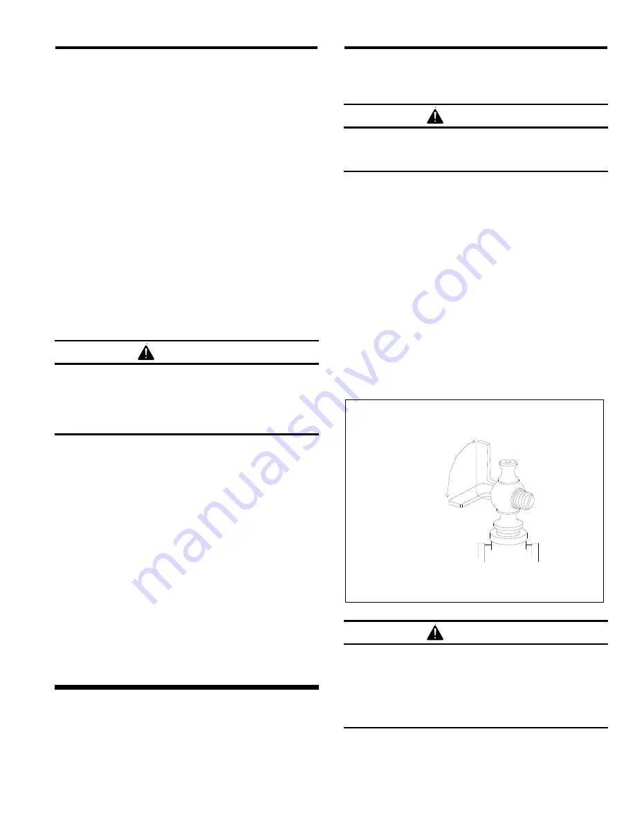
Make sure that the safety petcock located on the
inlet valve is open. The petcock is open when the
petcock lever is in-line with the petcock, as shown if
Figure 2.
Figure
2
Open
Closed
WARNING
To prevent severe injury from accidental
activation of the blast machine, open the safety
petcock when the blast machine is not in use.
Opening the petcock prevents unintentional
blasting. The control handle can not activate
the machine when the petcock is open.


