CLASSIC BLAST MACHINE with TLR-100/300 REMOTE CONTROLS
Page 7
© 2018 CLEMCO INDUSTRIES CORP.
www.clemcoindustries.com
Manual No. 22501, Rev. I 02/18
2.3.1
Where multiple blast machines are operating
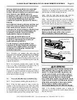
from a single air source, install a ball cone check valve
at the air supply on each machine. Refer to the
illustration in Figure 3 to install a check valve on a blast
machine.
2.3.2
If the machines are placed close together, use a
receiver tank or manifold and run separate air lines from it
to each machine. The check valves may be located on the
receiver tank outlets if the air line goes directly to the blast
machine and nowhere else.
NOTE:
Do not use a swing check valve, as the swing
gate may break in blast machine applications. When
installing the valve, make sure the directional arrow is
pointing in the direction of the air flow (toward the
machine).
2.3.3
Use a Clemco ball cone check valve shown
below. A smaller-size valve could restrict air movement
and reduce nozzle pressure.
TLR-100 with 1-NPT inlet valve
use 1-1/4-NPT check valve ......... Stock No. 02088
TLR-300, with1-1/2-NPT inlet valve
use 1-1/2-NPT check valve ......... Stock No. 02296
Figure
3
2.4
Install Optional Air Filter
(Moisture Separator) - Figure 4
The filter is included with blast machine systems.
2.4.1
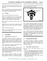
Install a compressed-air filter to the inlet valve
as shown in Figure 4. It is recommended that a filter be
installed at this location to remove moisture from air
before it enters the machine. If problems with moisture
persists after installing the filter, a dryer or aftercooler
may be required in the air-supply line.
Figure
4
2.5
Compressed-Air Supply Hose Connection
2.5.1
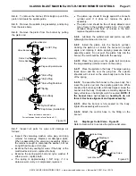
Apply thread sealant to the male pipe threads of
an air fitting that is compatible with the air supply hose
fitting, as noted in Section 2.5.2, and
install it onto the inlet
valve or optional air filter located at the blast machine
inlet, as shown in Figure 5. The style of connection shown
in Figure 5 is for reference only.
Figure
5
WARNING
Hose disconnection while under pressure can
cause serious injury or death. Use safety lock
pins or safety wire to lock twist-on (claw-type)
couplings together and prevent accidental
separation while under pressure and use
safety cables to prevent hose from whipping
should separation occur.
2.5.2
Attach an air line from the compressor to the
hose fitting installed on the blast machine inlet. For best
blasting performance, refer to the table in Figure 6 for
Ball Cone Check Valve
Close Nipple
Use a standard 1-1/4" x 1"
pipe bushing, Clemco Stock
No. 01804, when installing on
a TLR-100, 1" inlet valve.
Inlet Valve
Air Hose Adaptor
Air Supply Hose
Safety cable
Inlet Valve
Optional Air Filter


