CLASSIC BLAST MACHINE with TLR-100/300 REMOTE CONTROLS
Page 19
© 2018 CLEMCO INDUSTRIES CORP.
www.clemcoindustries.com
Manual No. 22501, Rev. I 02/18
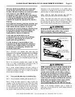
6.1.2.5
When the obstruction has been removed,
depressurize the machine. Remove the nozzle and
nozzle washer, and reattach the hose. Open the choke
valve and close the abrasive metering valve. Pressurize
the machine to clear the hose.
6.1.2.6
When the hose is cleared, depressurize the
machine so the nozzle and nozzle washer can be
reattached.
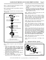
WARNING
The threads on the nozzle and nozzle holder
must be inspected each time the nozzle is
secured to the holder. A loose-fitting nozzle
may eject under pressure and cause severe
injury. Check the threads for wear and make
sure the nozzle holder securely holds the
nozzle. The nozzle washer must also be
inspected for wear. Worn nozzle washers can
cause thread erosion. A loose-fitting nozzle
may eject under pressure and can cause severe
injury.
6.1.2.7
Once the hose is cleared, start the machine
using normal procedures.
6.2
Clearing Obstructions in the Abrasive
Metering Valve and Blast Machine
6.2.1
If the nature of the obstruction permits emptying
the machine of abrasive,
follow the instructions,
per
Section 3.9.
6.2.2
Make sure the machine is depressurized. Turn
OFF the compressed-air supply. Lockout and tagout the
air supply, and bleed the air-supply line to the blast
machine.
6.2.3
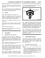
Remove the metering valve cleanout cover by
removing the wing nuts securing it.
6.2.4
Check the metering valve for blockage by
inserting a finger into the opening and feeling for an
obstruction or foreign object.
6.2.5
If the metering
valve is clear, remove the blast
machine inspection door and check inside for foreign
objects.
6.2.6
Make sure the inspection door gasket is in good
condition, and in place before re-bolting the door onto
the machine.
6.2.7
Make sure the abrasive metering-valve-
inspection-plate O-ring is in good condition and in place
before reassembling the inspection plate.
6.2.8
Check to make sure all inspection doors and
covers are secure before starting the compressed-air
supply.
6.3 Inlet
Valve
All service on the inlet valve must be done with the air
OFF and the air supply locked out and tagged out. It is
not necessary to remove the valve from the blast
machine.
6.3.1
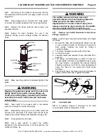
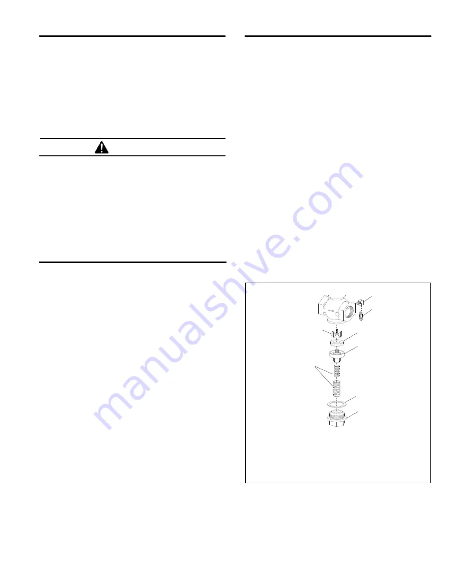
Bottom Section - Figure 17
6.3.1.1
Use a pipe wrench to loosen the bottom cap
until it can be removed by hand.
6.3.1.2
Use care when removing the cap as the
spring(s) (two are used in the 1-1/2
inlet valve) and plug
assembly could drop from the opening. Do not allow
them to fall to the ground as damage to the castings
could occur.
*Items included in service kit.
Figure
17
6.3.1.3
Clean all parts and inspect for wear as follows:
The small spring (only one used in 1
valve) is
approximately 1-11/16
long. If it is rusty or
compressed, replace it.
*Spring(s)
For replacement parts, refer to Sections
8.9 for 1-1/2" inlet valve part and
8.10 for 1" inlet valve parts.
One used in 1" valve.
Two used in 1-1/2"
l
Bottom Cap
*Bottom Cap Seal
*Valve Plug
*Valve-Plug Washer
Orifice Fitting
*Plug Retainer
Elbow


