I C S - 2 1 / 2 1 D T S P E A K E R S T A T I O N
2 - 1
QUICK START
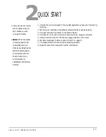
1. Unpack the unit and inspect it for any damage that may have occurred during
shipping.
2. Set the option switches to the default (toward the front panel) position.
3. Connect the RJ-45 connector to the Matrix frame.
4. Connect 14- to 18-VAC power to the two-terminal, plug-on connector.
5. Install the ICS-21/21DT into the four-gang outlet box or DT-Box.
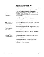
6. Set listen levels (see “Intercom-Level Control” on page 3).
7. The speaker station should now be operating properly.
8. Read the rest of this manual for further information.
• Users can use the “Quick
Start” approach to get
their stations up and
running in minutes.
• Note: When the station
is initially powered, the
call-waiting lamp will
blink slowly indicating the
station is attempting to
communicate with the
Matrix frame. Once
communication is
established, the blinking
will stop.
2
Summary of Contents for ICS-21
Page 1: ...SPEAKER STATION I N S T R U C T I O N M A N U A L ICS 21 21DT...
Page 4: ...I C S 2 1 2 1 D T S P E A K E R S T A T I O N...
Page 13: ...I C S 2 1 2 1 D T S P E A K E R S T A T I O N 1 9...
Page 15: ...I C S 2 1 2 1 D T S P E A K E R S T A T I O N...
Page 16: ...I C S 2 1 2 1 D T S P E A K E R S T A T I O N...
Page 18: ...I C S 2 1 2 1 D T S P E A K E R S T A T I O N...
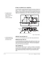
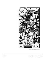
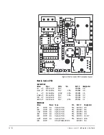
Page 22: ...I C S 2 1 2 1 D T S P E A K E R S T A T I O N 4 4 Figure 6 Main PCB Component Layout...

