I C S - 2 1 / 2 1 D T S P E A K E R S T A T I O N
1 - 7
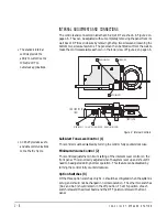
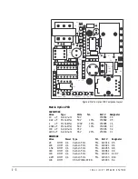
Internal Microphone Gain (S1-1)
This switch determines the microphone’s sensitivity. When the switch is in the
ON position (default), talking should be done within 2 ft. of the front panel. If it
is necessary to talk from a greater distance, the switch should be turned OFF.
Remotely Controlled Operation (S1-2 and S1-3)
These switches set either normal or remotely controlled operation. When they
are in the OFF position, operation is normal and the talk/listen function is
controlled by the Talk button. When they are in the ON position, the talk/
listen function is remotely controlled by another Matrix station. Both switches
must be in either the ON or OFF position. The ICS-21 will not function if S1-2
and S1-3 are in different positions.
Matrix Connector (4)
This eight-wire modular jack (RJ-45) provides an audio and data
communications link to the Matrix system.
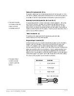
Program-Input Connector(5)
A three-terminal, plug-on connector provides the program input to the station.
Program is fed to the speaker. This level is controlled by the program-level
control. The program-input connector accepts a balanced or unbalanced
line-level audio signal from -20 dBv to +10 dBv. If this input is connected to the
stage announce (SA) output of a main station, it can be used as a paging input.
Because the level of this input is independently adjustable from the intercom
audio volume, it can be used to override the intercom audio in all modes except
remote listen-page. The program input is also independent of the mode setting.
The pinout of the program-input connector is as follows.
Table 2: Pinout Information
PIN NUMBER
FUNCTION
1
Ground (shield)
2
Positive signal
3
Negative signal
2
3
1
ICS-21/21DT PROGRAM
INPUT CONNECTOR
XLR CONNECTOR
PIN 1
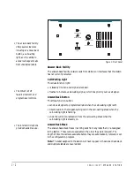
• The minimum-volume
control assures that the
volume cannot be
completely turned off.
• The program-input
connector provides
program input to the
station.
Summary of Contents for ICS-21
Page 1: ...SPEAKER STATION I N S T R U C T I O N M A N U A L ICS 21 21DT...
Page 4: ...I C S 2 1 2 1 D T S P E A K E R S T A T I O N...
Page 13: ...I C S 2 1 2 1 D T S P E A K E R S T A T I O N 1 9...
Page 15: ...I C S 2 1 2 1 D T S P E A K E R S T A T I O N...
Page 16: ...I C S 2 1 2 1 D T S P E A K E R S T A T I O N...
Page 18: ...I C S 2 1 2 1 D T S P E A K E R S T A T I O N...
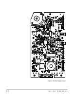
Page 22: ...I C S 2 1 2 1 D T S P E A K E R S T A T I O N 4 4 Figure 6 Main PCB Component Layout...

