I C S - 2 1 / 2 1 D T S P E A K E R S T A T I O N
1 - 4
Tone Alerts
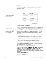
Tone alerts are set through the configuration program. The station has the
following three tones:
Table 1: Tone Alerts
REMOTELY CONTROLLED OPERATION
The ICS-21 can be programmed to be remotely controlled. This feature can be a
benefit when the ICS-21 is used in a location where it is not possible for the
person speaking on it to control it. This feature can also be used to remotely
monitor locations.
Remotely controlled operation must be enabled both in the ICS-21 and in the
Matrix System. To set remotely controlled operation in the ICS-21, use the
following steps:
1. Remove power from the ICS-21.
2. Remove or partially remove the ICS-21 from its outlet box or enclosure.
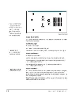
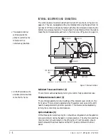
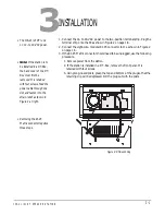
3. Set Option Switches S1-2 and S1-3 to the ON position, towards the front
panel. Refer to Figure 2.
4. Fasten the ICS-21 into its box or enclosure and reconnect power.
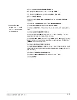
To set remotely controlled operation for the ICS-21 in the Matrix System, use
the following steps in PGM-WIN program:
1. From the
FILE
menu, select
ON-LINE TO MATRIX
.
2. From the
SETUP
menu, select
HARDWARE and LABELS
. Assign labels to
the stations by clicking on the
TALK LABEL
for the port the station is
connected to and typing in the label you want the station to have. For this
example, the ICS-21 station will be named ICS21 and the master station will be
named 2003.
3. Select the
ATTACHMENTS
tab.
4. Click on the
ROUTES
button.
TONE
MEANING
Four rapid beeps
Call signal
Two beeps
Label change
Single beep
Monitoring
• You can remotely control
the ICS-21 speaker
station.
• Remotely controlled
operation must be set up
both in the ICS-21 and in
the Matrix System.
Summary of Contents for ICS-21
Page 1: ...SPEAKER STATION I N S T R U C T I O N M A N U A L ICS 21 21DT...
Page 4: ...I C S 2 1 2 1 D T S P E A K E R S T A T I O N...
Page 13: ...I C S 2 1 2 1 D T S P E A K E R S T A T I O N 1 9...
Page 15: ...I C S 2 1 2 1 D T S P E A K E R S T A T I O N...
Page 16: ...I C S 2 1 2 1 D T S P E A K E R S T A T I O N...
Page 18: ...I C S 2 1 2 1 D T S P E A K E R S T A T I O N...
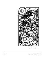
Page 22: ...I C S 2 1 2 1 D T S P E A K E R S T A T I O N 4 4 Figure 6 Main PCB Component Layout...

