I C S - 2 1 / 2 1 D T S P E A K E R S T A T I O N
i
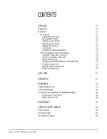
OPERATION
1-1
Description
1-1
Operation
1-1
Front Panel
1-1
Talk Button and Light
1-1
Answer-Back Facility
1-2
Intercom-Level Control
1-3
Program-Level Control
1-3
Integral Microphone
1-3
Tone Alerts
1-4
Remotely Controlled Operation
1-4
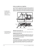
Internal Adjustments and Connections
1-6
Call-Alert Tone-Level Control (1)
1-6
Minimum-Volume Control (2)
1-6
Option Switches (3)
1-6
Remotely Controlled Operation (S1-2 and S1-3)
1-7
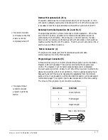
Matrix Connector (4)
1-7
Program-Input Connector(5)
1-7
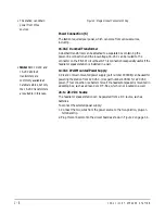
Power Connection (6)
1-8
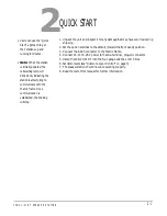
QUICK START
2-1
INSTALLATION
3-1
MAINTENANCE
4-1
Troubleshooting Tips
4-1
Technical Reference
4-3
Component Layouts/Bills of Materials/Schematics
4-4
ICS-21/21DT Main PCB
4-4
Matrix Option PCB
4-8
SPECIFICATIONS
5-1
CLEAR-COM LIMITED WARRANTY
6-1
Factory Service
6-1
Warranty Repair
6-1
Non-Warranty Repair
6-2
CONTENTS
Summary of Contents for ICS-21
Page 1: ...SPEAKER STATION I N S T R U C T I O N M A N U A L ICS 21 21DT...
Page 4: ...I C S 2 1 2 1 D T S P E A K E R S T A T I O N...
Page 13: ...I C S 2 1 2 1 D T S P E A K E R S T A T I O N 1 9...
Page 15: ...I C S 2 1 2 1 D T S P E A K E R S T A T I O N...
Page 16: ...I C S 2 1 2 1 D T S P E A K E R S T A T I O N...
Page 18: ...I C S 2 1 2 1 D T S P E A K E R S T A T I O N...
Page 22: ...I C S 2 1 2 1 D T S P E A K E R S T A T I O N 4 4 Figure 6 Main PCB Component Layout...

