I C S - 2 1 / 2 1 D T S P E A K E R S T A T I O N
4 - 1
MAINTENANCE
TROUBLESHOOTING TIPS
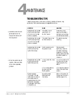
Listed below are some of the more common problems the station may
experience, their possible causes, and suggested solutions.
SYMPTOM
CAUSE
SOLUTION
System does not operate
and the talk light does
not turn on when talk
button is pressed.
The station is not
receiving 14- to
16-VAC power.
Check the circuit
powering the station
and make sure all plug
connections are secure.
System does not operate
and the talk light does
not turn on when talk
button is pressed.
The station has an has
an internal failure.
The station requires
servicing.
System does not operate
and the call-waiting
light blinks slowly.
Communication with
the system is lost.
Make sure each
eight-wire, modular
connector is securely
plugged in, check the
wiring, and ensure that
the Matrix system is
turned on.
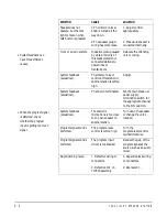
System does not operate
and the call-waiting
light blinks quickly.
1. S1-2 and/or S1-3 are
not off.
2. An incompatibility
problem with the
Matrix system.
1. Turn S1-2 and/or S1
off, then remove and
restore power to the
station.
2. Contact the dealer or
Clear-Com’s technical
service.
System operates
incorrectly. The talk
light does not come on
when talk button is
pressed or stays on until
talk button is pressed.
The speaker is off when
it should be on.
Operating mode
switches are set
incorrectly.
Refer to the section of
this manual on option
switches (page 1-5).
• Sometimes when the talk
light doesn’t work it’s
because the station isn’t
receiving power.
• When the system doesn’t
operate, make sure there
isn’t an incompatibility
problem.
4
Summary of Contents for ICS-21
Page 1: ...SPEAKER STATION I N S T R U C T I O N M A N U A L ICS 21 21DT...
Page 4: ...I C S 2 1 2 1 D T S P E A K E R S T A T I O N...
Page 13: ...I C S 2 1 2 1 D T S P E A K E R S T A T I O N 1 9...
Page 15: ...I C S 2 1 2 1 D T S P E A K E R S T A T I O N...
Page 16: ...I C S 2 1 2 1 D T S P E A K E R S T A T I O N...
Page 18: ...I C S 2 1 2 1 D T S P E A K E R S T A T I O N...
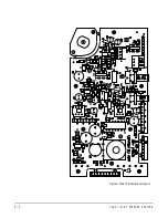
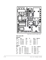
Page 22: ...I C S 2 1 2 1 D T S P E A K E R S T A T I O N 4 4 Figure 6 Main PCB Component Layout...

