


16
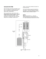
heat exchangers to the “Heat Max P.T.I” where it
is channeled through a series of stainless steel
tubing. The exhaust heat from the vacuum blower
is transferred to the stainless steel tubing,
boosting the temperature of the cleaning solution.
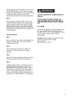
Step 4
The hot cleaning solution passes to the outlet
manifold, this manifold serves as a temperature
sensing point and connecting point for the high
pressure solution hoses. The cleaning solution
then passes through high pressure hoses and is
distributed by the cleaning tool to the surface that
is being cleaned.
Operating System
Step 1
Arriving at the job site, same routine applies: pre-
inspection, precondition, run hoses and tools
required into the site.
Step 2
Turn unit power on, then turn on pump, set
chemical meter and enter the site to begin
cleaning.
Step 3
Clean as normal using the recommended orifice
sizes listed below for the wand and stair tool.
Step 4
It will take approximately 15 minutes of normal
cleaning for the vacuum blower to generate
desired temperatures of 230ºF - 240ºF. As the
carpet wand vacuums the carpet it generates a
“load” on the vacuum blower, this in turn then
reaches and maintains optimum temperature for
maximizing the
“HEAT MAX P.T.I.” heat transfer.
DO NOT FREEZE! UNIT IS IRREPARABLE IF
FROZEN.
HOTTER WATER TEMPERATURES WILL
CAUSE PREMATURE DETERIORATION OF
HIGH PRESSURE HOSE, VALVES, ORINGS,
ETC.
JET SIZING
For maximum heat and overall unit performance,
the recommended floor tool jet sizing not to
exceed a total of “.045”. Using larger jet sizes on
your cleaning unit may reduce cleaning
temperatures.
Example:
Dual-jet wand uses two 110015 jets
(110º spray angle with 015 orifice).
015 x 2 = .03
Stair tool jet size: 11003
Summary of Contents for Compact 45
Page 1: ...VERSION AUG 2017...
Page 13: ...12...
Page 14: ...13...
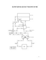
Page 18: ...17 WATER PUMPING AND HEAT TRANSFER SYSTEM...
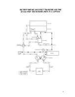
Page 19: ...18 WATER PUMPING AND HEAT TRANSFER SYSTEM DUAL HEAT EXCHANGER WITH P T I OPTION...
Page 28: ...27 CLEANCO COMPACT OVERHEAD VIEW...
Page 29: ...28...
Page 30: ...29 FRONT PANEL 45 47 FRONT VIEW...
Page 31: ...30 FRONT PANEL 45 47 BACK VIEW...
Page 33: ...32 FRONT PANEL PLUMBING P 1...
Page 34: ...33 FRONT PANEL PLUMBING P 2...
Page 37: ...36 COMPACT RECOVERY TANK...
Page 39: ...38 COMPACT BASEPLATE 45 47 P 1...
Page 40: ...39 COMPACT BASEPLATE 45 47 P 2...
Page 45: ...44 KIT INSTALLATION 45 47 P 1...
Page 46: ...45 KIT INSTALLATION 45 47 P 2...
Page 49: ...48 DUAL HEAT EXCHANGER...
Page 51: ...50 P T I...
Page 53: ...52 COVER HOLDER KIT...
Page 55: ...54 PTO SHAFT...
Page 58: ...57 C A D EXTERNAL OPTION PAGE 1...
Page 59: ...58 C A D EXTERNAL OPTION PAGE 2...
Page 61: ...60 F W TANK AQUA STORAGE 120 GALLON...
Page 63: ...62 F W TANK AQUA REEL TANK 125 GAL P 1...
Page 64: ...63 F W TANK AQUA REEL TANK 125 GAL P 2...
Page 75: ...74 CLEANCO COMPACT ELECTRIC WIRING P 1...
Page 76: ...75 CLEANCO COMPACT ELECTRIC WIRING P 2...
Page 77: ...76...
Page 78: ...77...
Page 79: ...78...
Page 80: ...79...
Page 81: ...80...
Page 82: ...81...
Page 83: ...82...
Page 84: ...83...