background image

PE 6001

DOUBLE SCISSOR LIFT 3T

GENERAL PRECAUTIONS

The operator, the installer and the maintenance fitter are required to observe the prescriptions 

of the safety regulation in force in the country of installation of the lift. 

Furthermore, the operator and maintenance fitter must: 
 

- Always work in the stations specified and illustrated in this manual;


- Never remove or deactivate the guards and the mechanical, electrical or other types of       


   safety devices;


- Read the safety notices placed on the lift and the safety information in this manual.

In the manual all safety notices are shown as follows:

WARNING

: indicates operations that are unsafe and can cause minor injury to persons and/or 

damage to the lift, the vehicle or other property. 

CAUTION:

 indicates possible danger that can result in serious injury to people and/or damage to 

properties. 

RISK  OF ELECTRIC SHOCK:

 a specific safety notice placed on the lift in areas where the risk of 

electric shock is particularly high. 

RISK AND PROTECTION DEVICES


We shall now examine the risks that operators or maintenance fitters may be exposed to when 

the vehicle is standing on the platforms in its raised position, together with the various safety and 

protection devices adopted by the manufacturer to reduce all such hazards to the minimum: 

For an optimal personal and vehicles safety, observe the following regulations:
 

- Do not enter the danger areas when vehicles are being lifted. (Picture 5)


- Make sure the vehicle is positioned correctly. (Picture 6)


- Be sure to lift only approved vehicles, never exceeding the specified carrying capacity, 


  maximum height, and projection (vehicle length and width);


- Make sure that there is no person on the platforms during up and down movements and 


  during the standing position.

GENERAL RISKS FOR LIFTING OR DESCENDANT PHASES: 

The following safety equipment is used to protect from over loading or from the possibility 

of engine failure. In the condition of over loading, the overflow valve will open and it will 

directly return the oil to its tank. (Picture 7)Each bottom of the oil cylinders are equipped 

with antiknock valve. If the oil pipe bursts, the specific valve will be activated and it will 

limit the lowering speed of the platforms.(Picture 8) 

Picture 6

Picture 7

Picture 8

SAFETY

Summary of Contents for PE 6001

Page 1: ...clas com DOUBLE SCISSOR LIFT 3T PE 6001...

Page 2: ...tions for use breakdown manufacturing problem please contact us Contact You can reach us by mail sav clas com or by phone 33 0 4 79 72 69 18 or go directly to our website clas com If you have changed...

Page 3: ...any other expense not specified in the supply contract are at the purchaser s charge The replacement and repair of parts under warranty anyway do not extend warranty terms The purchaser will neverthel...

Page 4: ...ded If finding missing parts possible defects or damages to the goods caused during the transport you should immediately inform the person in charge or the carrier The lifter is really heavy Don t mov...

Page 5: ...fting transport unpacking assembly installation starting up initial adjustment and testing extraordinary maintenance repair overhauls transport and dismantling of the lift are all operations that must...

Page 6: ...on doors Scissor lift is designed and built to lift all kinds of vehicles all other use are unauthorized In particular the lift is not suitable for washing spray work And do not lift vehicles whose we...

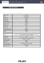
Page 7: ...Hydraulic oil Working temperature Working humidity Noise level Installation height Storage temperature Installation place PE 6001 Electrical hydraulic Hydraulic 3500kg 1950mm 105mm 1420mm 650mm 50s 6...

Page 8: ...PE 6001 DOUBLE SCISSOR LIFT 3T Lift dimension picture Picture 3...

Page 9: ...PE 6001 DOUBLE SCISSOR LIFT 3T Lift groundwork drawing for in ground installation Picture 4...

Page 10: ...f the lift platform nr P1 and nr P2 represents the concrete structure When the thickness of the inside level ground is less than 150mm the end of P1 and P2 should be taken to 2500 2500mm length and th...

Page 11: ...orms for personnel or lifting personnel Use as a press for crushing purposes Use as elevator Use as elevator for single parts of vehicles The manufacturer is not liable for any injury to persons or da...

Page 12: ...s that operators or maintenance fitters may be exposed to when the vehicle is standing on the platforms in its raised position together with the various safety and protection devices adopted by the ma...

Page 13: ...ght of the lifted vehicle or in the case the vehicle dimensions are not compatible with the capacity of the lift When the platform is being tested the vehicle engine cannot be turned on There is nothi...

Page 14: ...s it is perfectly leveled and sufficiently resistant 250 kg cm the thickness of concrete 150 mm All parts of the lift must be uniformly illuminated with enough light to make sure that the adjustment a...

Page 15: ...oil pipes be careful not to mistake the oil pipe Open the front cover on the control box Connection of power supply The three phase connection cables with 5 poles 400V 5 x 2 5 mm cable dimension are...

Page 16: ...te the MAIN SWITCH button to turn on the power by clicking the UP button proceed checking that the engine rotates clockwise by looking down if it s not turn off the MAIN SWITCH and then change the mot...

Page 17: ...leveling of the bases If the irregularity of the platforms is due to the irregularity of the bases use an iron thickness to level it After adjusting the level insert the anchor and use a hammer to se...

Page 18: ...o stop the process immediately Resolve the problem and repeat the test again Before any operation remove possible obstacles from the lifting area of the lift When lifting or lowering the platforms no...

Page 19: ...form press the EMERGENCY STOP button to stop the entire operating circuit and to interrupt any other operations HYDRAULIC OIL ADJUSTMENT normal conditions of use EMERGENCY PROCEDURE FOR PLATFORM MANUA...

Page 20: ...ower outlet The AC contactor does not work The limit switch is not closed The motor turns reverse Lifting with light load works normally but not with heavy load The hydraulic oil has a high viscosity...

Page 21: ...PE 6001 DOUBLE SCISSOR LIFT 3T Air circuit diagram only for mechanical lock version APPENDIX...

Page 22: ...PE 6001 DOUBLE SCISSOR LIFT 3T Hydraulic hose connection diagram APPENDIX...

Page 23: ...PE 6001 DOUBLE SCISSOR LIFT 3T Hydraulic diagram for the hydraulic lock version APPENDIX...

Page 24: ...PE 6001 DOUBLE SCISSOR LIFT 3T Electrical diagram 230V for the hydraulic lock version APPENDIX...

Page 25: ...PE 6001 DOUBLE SCISSOR LIFT 3T Electrical diagram 400V for the hydraulic lock version APPENDIX...

Page 26: ...ntactor thermal relay motor fuse power supply computer board power lamp emergency UP button DOWN button SEC DOWN button synchronization button photoelectric shield key switch buzzer descent valve work...

Page 27: ...PE 6001 DOUBLE SCISSOR LIFT 3T...

Page 28: ......

Page 29: ......

Page 30: ......

Page 31: ......

Page 32: ...parts please contact the reseller In case of problems please contact your authorized technician CLAS Equipements ZA de la CROUZA 73800 CHIGNIN FRANCE T l 33 0 4 79 72 62 22 Fax 33 0 4 79 72 52 86 PE 6...

Reviews: