background image

13

CHECKING THE OIL

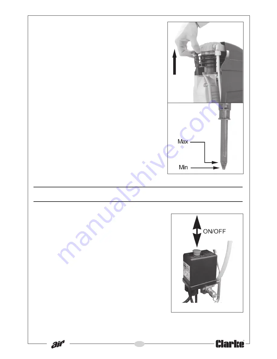
1. Remove dipstick and check the level of oil is

between the MAX and MIN marks as shown
in Fig 3. If not, top up to the correct level
with Clarke SAE40 compressor oil.

2. After the first 5 working hours, replace the oil

as described under MAINTENANCE on page
16.

OPERATING INSTRUCTIONS

STARTING THE COMPRESSOR

1. Pull the ON/OFF switch UP to start the

compressor as shown in Fig 4.

• The motor should start immediately, and

run, while the tank (reservoir) is being
pressurised.

2. When starting the compressor for the first

time, and before connecting it to the airline
equipment, leave it running for about 10
minutes to permit a good distribution of
lubricating oil.

• Observe that the compressor stops

automatically when the maximum
pressure of 8 bar is reached. The pressure
is indicated on the tank pressure gauge
shown in Fig 6.

Fig 3

Fig 4

Summary of Contents for PIONEER 220

Page 1: ...OPERATING MAINTENANCE INSTRUCTIONS GC0511 AIR COMPRESSOR Model No PIONEER 220 Part Nos 2320220 230V 2320221 110V...

Page 2: ...duct is found to have been abused or tampered with in any way or not used for its intended purpose Faulty goods should be returned to their place of purchase no product can be returned to us without p...

Page 3: ...ernational reserve the right to change specifications at any time without prior notice e r u t a e F n o i t a c i f i c e p S t h g i e W g k 2 2 m m H x W x L s n o i s n e m i D 0 3 6 x 0 2 3 x 5 9...

Page 4: ...EVER over reach Keep your proper footing and balance at all times to enable better control of the compressor in unexpected situations 5 NEVER attempt any complex repairs yourself If you have a technic...

Page 5: ...IRLINE HOSES 1 ALWAYS ensure that equipment or power tools used in conjunction with the compressor have a safe working pressure exceeding that of the machine 2 ALWAYS keep the air hose away from any a...

Page 6: ...ired by a qualified service engineer Do not use the compressor if the On Off switch does not operate correctly 7 KEEP THE MOTOR AIR VENTS CLEAR Keep the motor vents clear and free from dust Wipe regul...

Page 7: ...rrosive materials 4 DO NOT WIPE THE PLASTIC PARTS WITH SOLVENT Do not use solvents or thinners such as petrol benzene carbon tetrachloride or alcohol to clean the compressor as these chemicals will da...

Page 8: ...ue to damage it should be cut off and a replacement fitted following the wiring instructions shown below The old plug must be disposed of safely as insertion into a mains socket could cause an electri...

Page 9: ...LY IN THE EVENT OF A POWER CUT AND SUBSEQUENT RESET DO NOT CARRY THE COMPRESSOR WHILE IT IS CONNECTED TO THE POWER SOURCE OR WHEN THE TANK IS FILLED WITH COMPRESSED AIR THIS COMPRESSOR INCORPORATES SU...

Page 10: ...10 OVERVIEW...

Page 11: ...place a strain on the airline fittings or hoses Take care when moving the compressor to avoid damaging the valves or fittings Always ensure it is switched off and disconnect from the mains power suppl...

Page 12: ...er compressed air is DANGEROUS WARNING Before connecting any air tool make sure you have read and fully understood the manufacturer s instruction booklet for the air tool being used Also ensure that t...

Page 13: ...R 1 Pull the ON OFF switch UP to start the compressor as shown in Fig 4 The motor should start immediately and run while the tank reservoir is being pressurised 2 When starting the compressor for the...

Page 14: ...cap of the regulator towards you 2 Turn the pressure regulator knob clockwise to increase pressure and anticlockwise to decrease pressure The pressure setting will be displayed by the outlet pressure...

Page 15: ...shut off the compressor Never stop the compressor by unplugging it from the power supply It should be turned off as above 2 After use set the outlet pressure back to zero 3 Operate the trigger of all...

Page 16: ...ilter element shown in Fig 8 for cleanliness If necessary it may be gently washed in warm soapy water Rinse and allow to dry thoroughly before refitting This should be done more frequently if the comp...

Page 17: ...2 YEARS Check the non return valve and if necessary replace the gasket O ring shown in Fig 11 IMPORTANT The use of parts other than Clarke replacement parts may result in safety hazards poor performa...

Page 18: ...a g n i t t e s e h t s e h c a e r e r u s s e r p l o r t n o c e r u s s e r p e h t f o i s p 5 9 x o r p p a h c t i w s e h t m o r f g n i k a e l d n u o f r i A e v l a v h c t i w s e r u s...

Page 19: ...L 0 0 0 1 5 7 1 1 0 N F 1 6 E V L A V N R U T E R N O N 0 0 0 2 9 0 7 4 3 N F 1 1 2 E G U A G E R U S S E R P 0 0 0 6 0 0 0 3 3 N F 2 7 T E K S A G 0 0 0 7 5 3 9 9 F N F 1 2 2 G N I L P U O C T I F K...

Page 20: ...20 PARTS DIAGRAM AIR RECEIVER CONTROLS...

Page 21: ...21 PARTS DIAGRAM COMPRESSOR...

Page 22: ...1 1 T U N 0 1 0 0 9 1 1 6 1 N F 3 3 3 T E K S A G D A E H 4 1 0 0 2 1 6 1 1 N F 1 2 1 T U N 8 1 0 3 0 0 4 1 0 N F 2 4 3 E T A L P E V L A V 0 0 1 0 2 1 6 1 1 N F 1 3 1 R O T I C A P A C 4 0 0 0 0 2 9...

Page 23: ...23 DECLARATION OF CONFORMITY...

Page 24: ......

Reviews: