15
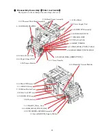
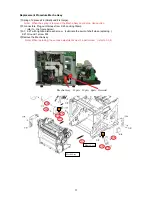
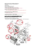
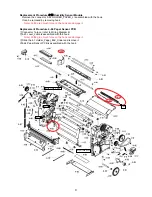
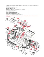
Replacement Procedure 2-32 Thermal Print Head Assembly
①
Remove 2-19
,Remove
2-2
②
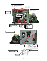
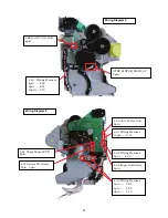
Remove Connector 10 pin FFC 28pin(470mm), 22pin(505mm)
Note
)
Be sure to unlock the connector when inserting and removing the FFC.FFC is fixed with the
double-side tape.
③
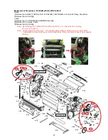
Remove
screws) Remove 2-32
Thermal Print Head Assembly
④
Replace
2-32
Thermal Print Head Assembly
Note
)
Torque 0.30
±
0.05N
・
m
If the screw torque is incorrect, it could be detrimental to print quality.
When installing the Thermal Print Head Assembly, the positioning pins must be lined up. Be sure
to align them and install it so there is no gap.
⑤
Instet Connector 10 pin FFC 28pin(470mm), 22pin(505mm)
⑥
Thermal Print Head Assembly, set the resistance value. (refer to Ch.4)
FFC 22pin
10 pin
FFC 28pin
Flame Assy
Mecha Assy

