18
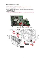
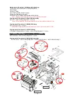
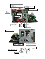
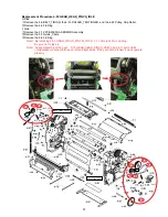
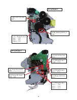
Replacement Procedure 2-29 Head Frame Assembly
①
connectors
(
refer to the figure below
)
②
2-3 PLATE_HEAD_Holder 2 screws
③
2-7 Spring
Note) When the spring is removed, the Mecha Assy could drop. Use caution.
④
Slide the Head Assy right and lift it up.
Note
)
Note) Be careful of the Ribbon Rewind Assy gear when sliding it.
Note) ) When replacing, the various adjustments must be performed
(refer to Ch.4)
Mecha Assy
Flame Assy
Head Assy
10pin
4pin
Front
The attachment direction


