5-61
Cisco XR 12416 and Cisco XR 12816 Router Chassis Installation Guide
OL-17440-01
Chapter 5 Maintaining the Router
Removing and Replacing a Power Bus Board Fuse
Installing the Replacement Chassis
Use the following procedure to install the replacement rack in the chassis.
Step 1
Disconnect the temporary ground connections to the replacement chassis.
Step 2
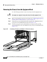
Install the chassis into the rack (see
Rack-Mounting the Router Chassis,
page 3-6
).
Step 3
Connect all ground connections to the chassis (see
Supplemental Bonding and
Grounding Connections, page 3-19
).
Step 4
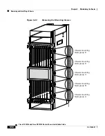
Attach the vertical cable management troughs (see
Attaching the Vertical
Cable-Management Trough, page 3-23
).
Step 5
Connect all line card interface cables using the notes and labeling you created
when disconnecting them from the defective chassis.
Step 6
Connect power cables to the router (see
Connecting Power to the Power Shelf,
page 3-34
).
Step 7
Power on the router.
Removing and Replacing a Power Bus Board Fuse
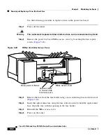
There are two user-replaceable fuses on the power bus board inside the power
interface panel:
•
The fuse labeled F1 protects the MBus controller module.
•
The fuse labeled F2 protects the 5.1 VDC bias voltage for the current
monitoring (Imon) signal and the voltage monitoring (Vmon) signals on AC
power subsystems.
Note
Fuse F2 is used only in AC-input power shelves. It is not used in DC-input power
shelves. Spane fuses can be ordered from Cisco as part number:
PWR-2A/125V-FUSE=.

