5-11
Cisco XR 12416 and Cisco XR 12816 Router Chassis Installation Guide
OL-17440-01
Chapter 5 Maintaining the Router
Removing and Replacing Blower Modules
Upper and Lower Blower Module Orientation
Illustrations in this procedure show the removal and replacement of the upper
blower module. The procedure to replace the lower blower module is the same
except for the orientation of the blower module
.
•
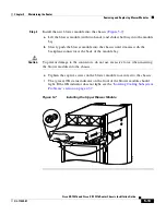
Heads-up orientation—Install the blower module in the upper bay in the
“heads-up” orientation with the three fan air intake openings face down.
•
Heads-down orientation—Install the blower module in the lower blower
module bay in the “heads-down” orientation with the three fan air intake
openings face up.
Use the following procedure to remove and replace the blower modules.
Step 1
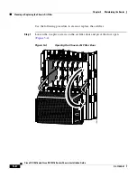
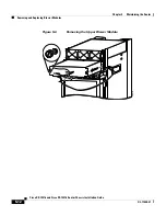
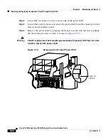
Remove the blower module from the chassis (
Figure 5-6
):
a.
Loosen the captive screw on each side of the blower module.
b.
Pull out the blower module halfway from the module bay.
c.
Slide out the blower module completely from the module bay while
supporting it with your other hand.
Warning
The blower module weighs approximately 20 pounds (9 kg). Use two hands
when handling the blower module.


