Both grids in a power redundant system should have the same number of power supplies. If your system is
configured for grid power (N+N redundancy), slots 1 and 2 are assigned to grid 1 and slots 3 and 4 are assigned
to grid 2. If there are only two power supplies in a redundant- mode chassis, they should be in slots 1 and 3.
This would be a very unusual configuration, with a single compute node in the chassis. A larger configuration
would require two power supplies per grid. Slot and cord connection numbering is shown below.
Note
Removing a Power Supply
If you are using the Cisco UCS X9508 server chassis with one power supply, which is a non-redundant power
configuration. Removing the power supply will cause the compute nodes and chassis to shut down. If you are
using more than two power supplies, and you remove one of them (the minimum supported power configuration
is 3 PSUs), the servers continue to operate as long as the other power supplies are sufficient to meet the power
requirements of the number of compute nodes in the chassis.
Caution
The PSU has a locking latch that secures the PSU in the chassis. You must unlock the latch to remove the
PSU. You can expect some resistance as the PSU slides out due to its weight.
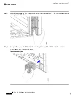
Step 1
Place your thumb on the PSU locking latch at the vertical fingerhold on the right side of the blank's faceplate and allow
your other fingers to rest along the side of the chassis.
Step 2
Press the latch to unlock the PSU, then pull until it disengages from the power socket inside the chassis.
You will feel some resistance initially as the connector at the rear of the PSU unseats from the power socket inside the
chassis.
Step 3
As you slide the PSU out of the chassis, use your other hand to support the PSU.
Cisco UCS X9508 Server Chassis Installation Guide
72
Installing and Removing Components
Removing a Power Supply
Summary of Contents for UCS X9508
Page 6: ...Cisco UCS X9508 Server Chassis Installation Guide vi Contents ...
Page 26: ...Cisco UCS X9508 Server Chassis Installation Guide 18 Overview Interpreting LEDs ...
Page 31: ...Cisco UCS X9508 Server Chassis Installation Guide 23 Installation Handling the Chassis ...
Page 64: ...Cisco UCS X9508 Server Chassis Installation Guide 56 Installation Repacking the Chassis ...
Page 124: ...Cisco UCS X9508 Server Chassis Installation Guide 116 Technical Specifications Switzerland ...


