Step 1
Verify that all the front and rear mounting screws for the rails and the chassis are tight, and the chassis is secured to the
rack.
Step 2
At the front of the chassis, attach the side trim panels.
The side trim panels attach magnetically, so you don't need any tools.
Step 3
Making sure that all people and equipment are not under the chassis, lower and remove the lift.
Step 4
Install any additional IFMs, PSUs, compute nodes or other chassis components, if needed.
Step 5
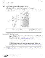
To power up the chassis, connect the appropriate power cables to the inlet connector corresponding to each installed
power supply, and then connect the other end of the cables to the power source. To determine the number of power
supplies needed for a given configuration, use the
tool.
Both grids in a power redundant system should have the same number of power supplies. If your system is
configured for grid power (N+N redundancy), slots 1 and 2 are assigned to grid 1 and slots 3 and 4 are assigned
to grid 2. If only two power supplies (PS) are in a redundant- mode chassis, they should be in slots 1 and 3.
Slot and cord connection numbering is shown below.
Note
Step 6
Attach any remaining cables to provide fabric connectivity for the chassis and compute nodes and do a visual inspection
of LEDs to ensure the chassis and its components are operating in runtime.
Choosing Earth Ground Option
The Cisco UCS X9508 server chassis supports connection to facility earth ground through either of the
following options:
• side mount, which supports connecting the ground cable directly to the chassis through a ground point
on one side of the chassis. For this option, go to
Connecting Side-Mount Earth Ground, on page 46
• rear mount, which supports connecting the ground cable to a ground bracket that attaches to one of the
rear mounting brackets at the rear of the chassis. For this option, go to
.
Choose the option that is appropriate for your installation. Both options require you to assemble the ground
cable by crimping a ground lug onto the end of the ground cable. For information about the ground lug, see
"Ground Lug" in
Earth Ground Considerations, on page 21
Connecting Side-Mount Earth Ground
To connect side-mount earth ground you will connect a ground lug to a ground cable, then attach the cable
to the designated earth ground point on the chassis sheet metal. The designated earth ground is on the side of
the chassis.
The chassis also has a rear-mount option for earth ground by using a specific ground bracket that attaches to
the rear of the chassis. For more information, see
Connecting Rear-Mount Earth Ground, on page 48
.
Note
The facility ground cable must be terminated with the groung lug provided by Cisco, or an equivalent. For
more information, see "Ground Lug" in
Earth Ground Considerations, on page 21
.
Cisco UCS X9508 Server Chassis Installation Guide
46
Installation
Choosing Earth Ground Option
Summary of Contents for UCS X9508
Page 6: ...Cisco UCS X9508 Server Chassis Installation Guide vi Contents ...
Page 26: ...Cisco UCS X9508 Server Chassis Installation Guide 18 Overview Interpreting LEDs ...
Page 31: ...Cisco UCS X9508 Server Chassis Installation Guide 23 Installation Handling the Chassis ...
Page 64: ...Cisco UCS X9508 Server Chassis Installation Guide 56 Installation Repacking the Chassis ...
Page 124: ...Cisco UCS X9508 Server Chassis Installation Guide 116 Technical Specifications Switzerland ...


