background image

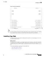
Figure 11: Rack Installation Template, Rear

The eight cage nuts shown near the top of the template (four per side) are required only when you are installing
the rear tie down brackets, which are an orderable option, but not required for basic installation.

Note

Installing Cage Nuts

For untapped equipment racks, you must install cage nuts to provide a way for mounting screws to secure
rails and the chassis to the rack.

Before you begin

This document provides illustrations of installation templates for the front and rear of the chassis. The templates
are designed to show you the proper holes within which the rails and cage nuts should be placed. Once you
align the rack holes line up with the template, you should mark the holes on the rack so that they are easy to
use.

To use the rack installation templates, go to the appropriate topic:

Front Install Template, on page 27

Rear Install Template, on page 28

Cisco UCS X9508 Server Chassis Installation Guide

29

Installation

Installing Cage Nuts

Summary of Contents for UCS X9508

Page 1: ... Installation Guide First Published 2021 07 30 Last Modified 2021 08 20 Americas Headquarters Cisco Systems Inc 170 West Tasman Drive San Jose CA 95134 1706 USA http www cisco com Tel 408 526 4000 800 553 NETS 6387 Fax 408 527 0883 ...

Page 2: ...o UCS 9108 25G Intelligent Fabric Module 7 Cisco UCS X Fabric Module Blanks 8 Fan Modules 8 Power Supplies 9 LEDs 10 Buttons 10 Connectors 10 Power Supply Configuration 10 Non Redundant Mode 11 N 1 Power Supply Configuration 11 N 2 Power Supply Configuration 12 Grid Configuration 12 LEDs 13 LED Locations 13 Interpreting LEDs 14 Installation 19 C H A P T E R 2 Cisco UCS X9508 Server Chassis Install...

Page 3: ...on Layout 35 Installing the Top Cable Management Arms 37 Installing the Ground Bracket and Bottom Cable Management Arms 39 Inserting the Chassis into the Rack 40 Installing Rear Mounting Brackets 43 Completing Installation 45 Choosing Earth Ground Option 46 Connecting Side Mount Earth Ground 46 Connecting Rear Mount Earth Ground 48 Attaching Cable Management Trays 50 Installing the Cable Managemen...

Page 4: ...s 79 Removing the Power Entry Modules 81 Installing and Removing a Fan Module 84 Installing a Fan Module 84 Removing a Fan Module 85 Installing and Removing a Rear Module s Fan 87 Installing a Fan for a UCS Intelligent Fabric Module IFM or X Fabric Module XFM Blank 88 Removing a Fan for a UCS Intelligent Fabric Module IFM or X Fabric Module XFM Blank 89 Installing and Removing an Intelligent Fabri...

Page 5: ...Power Cords and Plugs 111 Australia and New Zealand 112 Continental Europe 112 International 112 Israel 113 Japan and North America 113 Peoples Republic of China 114 Taiwan 115 Switzerland 115 Site Planning and Maintenance Records 117 A P P E N D I X B Site Preparation Checklist 117 Contact and Site Information 119 Chassis and Module Information 120 FEX Port Connection Record 121 UCS 6548 Fabric I...

Page 6: ...Cisco UCS X9508 Server Chassis Installation Guide vi Contents ...

Page 7: ...C approval and negate your authority to operate the product The Cisco implementation of TCP header compression is an adaptation of a program developed by the University of California Berkeley UCB as part of UCB s public domain version of the UNIX operating system All rights reserved Copyright 1981 Regents of the University of California NOTWITHSTANDING ANY OTHER WARRANTY HEREIN ALL DOCUMENT FILES ...

Page 8: ...a web based tool that acts as a gateway to the Cisco bug tracking system that maintains a comprehensive list of defects and vulnerabilities in Cisco products and software BST provides you with detailed defect information about your products and software ...

Page 9: ...erver and data management All servers are managed through the GUI or API with Cisco Intersight The Cisco UCS X9508 Server Chassis system consists of the following components Chassis versions Cisco UCS X9508 server chassis AC version Intelligent Fabric Modules IFMs two deployed as a pair Cisco UCS 9108 25G IFMs UCSX I 9108 25G Two I O modules each with 8 25 Gigabit SFP28 optical ports Power supplie...

Page 10: ... LEDs Locator LED Button System Status LED Network Link LED For information about System LEDs see LEDs on page 13 1 System Asset Tag 4 Power Supplies a maximum of 6 3 System side panels two which are removable The side panels cover the rack mounting brackets 5 Cisco UCS X9508 Server Chassis Installation Guide 2 Overview System Overview ...

Page 11: ...for facility inlet power Each PEM contains 3 IEC 320 C20 inlets PEM 1 is at the top of the chassis and it supports IEC inlets 1 through 3 with inlet 1 at the top of PEM 1 PEM 2 is at the bottom of chassis and it supports IEC inlets 4 through 6 with inlet 4 at the top of PEM 2 1 Expansion slots two 4 System fans four 3 Cisco UCS X9508 Server Chassis Installation Guide 3 Overview System Overview ...

Page 12: ...res and Benefits Benefit Feature Reduces total cost of ownership by removing management modules from the chassis making the chassis stateless Provides a single highly available cloud based management tool for all server chassis IFMs and compute nodes thus reducing administrative tasks Management by Cisco Intersight Decreases TCO by reducing the number of network interface cards NICs host bus adapt...

Page 13: ...bps PCIe Gen5 Direct node to fabric connectivity Provides high availability in multiple configurations Increases serviceability Provides uninterrupted service during maintenance Available configured for AC environments mixing not supported Redundant hot swappable power supplies and fans Provides uninterrupted service during maintenance and server deployment Hot pluggable compute nodes and intellig...

Page 14: ...eries compute nodes are based on industry standard server technologies and provide the following Up to two Intel multi core processors Front accessible hot swappable NVMe drives or solid state disk SSD drives Depending on the compute node support is available for up to two adapter card connections for up to 200 Gbps of redundant I O throughput Industry standard double data rate 4 DDR4 memory Remot...

Page 15: ...through IFMs Compute Node health IFMs monitor Keyboard Video Mouse KVM data Serial over LAN SoL data and IPMI data for the compute nodes in the chassis as well as provide management of these features IFMs must always be deployed in pairs to provide redundancy and failover to safeguard system operation Cisco UCS 9108 25G Intelligent Fabric Module The Cisco UCS 9108 Intelligent Fabric Module UCSX I ...

Page 16: ...figuration this module blank can be installed in either of the two bottom slots in the rear of the chassis below the IFM slots Figure 5 UCS X9508 Rear Module Blank Faceplate View Module Ejector Handles Left and Right 2 Status LEDs Module Status top LED Fan Status LEDs 1 through 3 with Fan 1 as LED 2 Fan 2 as LED 3 and Fan 3 as LED 4 1 Fan Modules The chassis contains 4 fan modules with the minimum...

Page 17: ...y configuration where N is the number of power supplies required to support system power requirements N 2 power supply configuration where N is the number of power supplies required to support system power requirements Grid configuration which is also known as N N power supply configuration in which N is the amount of power supplies required to support the system power requirements The chassis req...

Page 18: ...nto consideration AC power supplies are all single phase and have a single input for connectivity to its respective PEM The customer power source a rack PDU or equivalent connects input power directly to the chassis power entry module PEM not the actual AC power supplies The number of power supplies required to power a chassis varies depending on the following factors The total Maximum Draw requir...

Page 19: ... supplies Note N 1 Power Supply Configuration In an N 1 configuration the chassis contains a total number of power supplies to satisfy system power requirements plus one additional power supply for redundancy In an N 1 configuration a maximum power of 14kW is delivered with five PSUs configured as Active while the remaining one PSU is in standby mode The 14kW maximum delivered power is only possib...

Page 20: ...ree PSUs has its own input power circuit so each set of PSUs is isolated from any failures that might affect the other set of PSUs If one input power source fails causing a loss of power to three power supplies the surviving power supplies on the other power circuit continue to provide power to the chassis Grid redundant mode requires the chassis load to be limited to 8 4KW for high input voltage ...

Page 21: ...her LEDs LED Locations The UCS X9508 server chassis uses LEDs to indicate power status location identification Other LEDs on IFMs PSUs fans and compute nodes indicate status information for those elements of the system Figure 8 LEDs on a Cisco UCS X9508 Server Chassis Front View Cisco UCS X9508 Server Chassis Installation Guide 13 Overview LEDs ...

Page 22: ...ply LEDs Description Color LED Locator not enabled Off Locator LED and button callout 1 on the chassis front panel Locates a selected chassis You can initiate beaconing in UCS Intersight or with the button which toggles the LED on and off Blue Cisco UCS X9508 Server Chassis Installation Guide 14 Overview Interpreting LEDs ...

Page 23: ...id amber System Status callout 1 on the chassis front panel Normal operating condition Solid Green Chassis is in a critical error state For example Boot Failure Fatal Processor and or bus error detected Loss of both I O Modules Over Temperature Condition Blinking Amber System is in an undefined operational state or not receiving power Off No power to the chassis or the fan module was removed from ...

Page 24: ...detected Some examples Over voltage warning Over temperature warning Blinking Amber Table 3 Intelligent Fabric Module and Rear Module Blank LEDs Description Color LED No power Off Module Status callout 1 and 4 on the Chassis Rear Panel Normal operation Green Booting or minor temperature alarm Amber POST error or other error condition Blinking amber Link down Off Module Fans callout 1 and 4 the Cha...

Page 25: ...Off Compute Node Locator LED and button callout 3 on the Chassis Front Panel Locates a selected compute node If the LED is not blinking the compute node is not selected You can initiate the LED in UCS Intersight or by pressing the button which toggles the LED on and off Blinking Blue 1 Hz Inactive Off Drive Activity Outstanding I O to disk drive Green No fault detected the drive is not installed o...

Page 26: ...Cisco UCS X9508 Server Chassis Installation Guide 18 Overview Interpreting LEDs ...

Page 27: ...on for Cisco UCS for important safety information Note IMPORTANT SAFETY INSTRUCTIONS This warning symbol means danger You are in a situation that could cause bodily injury Before you work on any equipment be aware of the hazards involved with electrical circuitry and be familiar with standard practices for preventing accidents Use the statement number provided at the end of each warning to locate ...

Page 28: ...ks that have obstructions These obstructions could impair access to field replaceable units FRUs Note Cisco UCS is compliant with any EIA 310 D E compliant rack Your equipment racks must also be compliant with EIA 310 D E standard Also be aware of these additional requirements The tool less rack mount kits either Type 1 or Type 2 shipped with the chassis are required The adjustable rack rails ship...

Page 29: ...must be grounded Never defeat the ground conductor or operate the equipment in the absence of a suitably installed ground conductor Contact the appropriate electrical inspection authority or an electrician if you are uncertain that suitable grounding is available Statement 1024 Warning For Nordic countries Norway Finland Sweden and Denmark this system must be installed in a Restricted Access Locat...

Page 30: ...er to center Note Handling the Chassis As a best practice handle the chassis when it is empty and use either a scissors jack or multiple people to bear the weight The Cisco UCS X9508 has defined areas for holding the chassis grasp points Grasp points are not indicated on the chassis itself but facilitate handling or moving the chassis Watch your hands and fingers whenever you handle the chassis mo...

Page 31: ...Cisco UCS X9508 Server Chassis Installation Guide 23 Installation Handling the Chassis ...

Page 32: ...ts Do not lift or handle the chassis by the top rear sheet metal as indicated by the DO NOT LIFT label on the top rear surface Note Cisco UCS X9508 Server Chassis Installation Guide 24 Installation Handling the Chassis ...

Page 33: ...see the Cisco UCS Site Preparation Guide Record the information listed in Site Planning and Maintenance Records on page 117 as you install and configure the chassis Ensure that there is adequate space around the chassis to allow for servicing the chassis and for airflow Ensure that the air conditioning meets the heat dissipation requirements listed in Technical Specifications on page 107 Ensure th...

Page 34: ...tic foam Unpacking and Inspecting the Chassis When handling chassis components wear an ESD strap and handle modules by the carrier edges only Caution Keep the shipping container in case the chassis requires shipping in the future Tip The chassis is thoroughly inspected before shipment If any damage occurred during transportation or any items are missing contact your customer service representative...

Page 35: ...nce through the following sections of this document The templates show the locations on the rack for cage nuts rail kit locator pegs and screws should be installed The templates facilitate installing the rail kit and chassis by ensuring proper spacing and alignment of installation hardware in both the left and right sides of the rack The chassis has one template for the front of the rack and one f...

Page 36: ...ting hardware on the rack This template shows the rack locations for mounting the rear of the chassis Align the Chassis Top of the template with the location in the rack where the top of the chassis will be and install the cage nuts and other hardware as shown Cisco UCS X9508 Server Chassis Installation Guide 28 Installation Rear Install Template ...

Page 37: ...e chassis to the rack Before you begin This document provides illustrations of installation templates for the front and rear of the chassis The templates are designed to show you the proper holes within which the rails and cage nuts should be placed Once you align the rack holes line up with the template you should mark the holes on the rack so that they are easy to use To use the rack installatio...

Page 38: ...ide of the rack so that most of the nut is behind the rack s sheet metal Note Figure 12 Cage Nut Installation Step 5 Verify that the cage nut is fully and correctly installed before installing the remaining cage nuts Rail Kits The Cisco UCS X9508 supports two rail kits Type 1 and Type 2 Each rail kit consists of two stationary rails that facilitate rack installation of the chassis and stabilize th...

Page 39: ...nt of 4 chassis the shipment might have all one type of rail kit or a few chassis with each type of rail kit Compare the two types of rail kits Figure 13 Two Types of Rail Kits The rail kits are similar in size function and construction with a few exceptions the type of release tab at the top corner of the rail the type of locator pegs either round or square which temporarily hold the rail in the ...

Page 40: ...y power make sure not to overload the capacity of a PDU or power strip For example do not connect all PSUs to one PDU or power strip that is not capable of carrying the total power draw of the chassis Caution Watch your hands and fingers whenever you handle the chassis modules compute nodes and components Narrow vertical or horizontal spaces in situations including but not limited to moving the ch...

Page 41: ...he locator pegs will hold the rail in the rack so that you don t have to hold the rail in place Step 3 At the rear of the rack use the rear installation template to position the two locator pegs on the rail with the corresponding location in the rack See Rear Install Template on page 28 Step 4 Repeat the previous steps to install the other rack rail Figure 14 Install Rails into Front of the Rack S...

Page 42: ... the Rack Step 7 At the rear of the rack refer to the template then insert a screw in each rear rail to secure each rail to the rack at the correct location Cisco UCS X9508 Server Chassis Installation Guide 34 Installation Installing the Rails ...

Page 43: ... page 35 Rail Installation Layout Before installing the chassis in the rack compare the rail installation in the rack against the following layout images If the rail installation is different than what is shown in each layout remove the rails and reinstall them Cisco UCS X9508 Server Chassis Installation Guide 35 Installation Rail Installation Layout ...

Page 44: ...Figure 17 Front Rail Layout Both Rail Kits Cisco UCS X9508 Server Chassis Installation Guide 36 Installation Rail Installation Layout ...

Page 45: ...the location on the chassis Cable management arms are interchangeable so there is no specific top and bottom cable arm Each cable management assembly is for a set of three PSUs The top cable management arms attach to the top set of PSUs in the chassis The bottom cable management arms attach a grounding bracket for the bottom set of PSUs so the installation procedure is slightly different See Insta...

Page 46: ...r chassis by tightening the captive screws Figure 19 Attaching the Top Cable Management Arms to the Chassis Step 3 Adjust the cable tie horizontally to align with where you wish to grasp the power cable Step 4 You can use the cable ties to gather the power cables and secure the plugs in place Cisco UCS X9508 Server Chassis Installation Guide 38 Installation Installing the Top Cable Management Arms...

Page 47: ...his topic top and bottom refer to the location on the chassis Cable management arms are interchangeable so there is no specific top and bottom cable arm Note For the additional ground requirements see Earth Ground Considerations on page 21 Attach the ground bracket and bottom cable management arms to the chassis a Align the long side of the ground bracket with the threaded standoff on the chassis ...

Page 48: ...the front and rear layouts do so now See Rail Installation Layout on page 35 Also make sure to review Installation Notes and Warnings for the Cisco UCS X9508 Server Chassis on page 19 The chassis must be grounded by a ground lug that Cisco provides or an equivalent See Ground Lug in Earth Ground Considerations on page 21 Before beginning this procedure make sure that the rails are correctly instal...

Page 49: ...onal people to help you Tip Step 1 Using a scissor jack chassis lift or other mechanical device lift the chassis and position it so that you can slide it into the rack Step 2 Slide the chassis into the rack until the front flange is flat against the cage nuts Figure 21 Inserting the Chassis into the Rack Step 3 At the front of the chassis remove each of the side trim panels from the chassis The si...

Page 50: ...p 4 At the front of the chassis use a 3 Phillips head screwdriver to insert and tighten the eight M6 x 20mm screws through the front mounting flanges Cisco UCS X9508 Server Chassis Installation Guide 42 Installation Inserting the Chassis into the Rack ...

Page 51: ...hippable rack attach the rear mounting brackets See Installing Rear Mounting Brackets on page 43 b If you will be installing the chassis in a stationary rack continue the installation procedure See Completing Installation on page 45 Installing Rear Mounting Brackets Use this procedure to install the rear mounting tie down brackets Cisco UCS X9508 Server Chassis Installation Guide 43 Installation I...

Page 52: ...ok the into the cutout in the chassis side wall b Slide each rear mounting bracket until the tab seats into the emboss in the chassis top Figure 24 Attaching the Rear Mounting Brackets Step 2 Holding the rear mounting brackets in place use the 3 Phillips head screwdriver to insert the 8 M6 x 20mm screws through the rear mounting brackets then tighten the screws to secure the rear of the chassis to...

Page 53: ...k What to do next Complete installing the chassis into the rack Go to Completing Installation on page 45 Completing Installation Continue with installing the chassis Cisco UCS X9508 Server Chassis Installation Guide 45 Installation Completing Installation ...

Page 54: ...th Ground Option The Cisco UCS X9508 server chassis supports connection to facility earth ground through either of the following options side mount which supports connecting the ground cable directly to the chassis through a ground point on one side of the chassis For this option go to Connecting Side Mount Earth Ground on page 46 rear mount which supports connecting the ground cable to a ground b...

Page 55: ...end 6 AWG wire for the U S installations Make sure to use the proper grounding cable and grounding wire as appropriate for your country or region c Use a crimping tool to secure the grounding cable in the grounding lug d Prepare the other end of the grounding cable and connect it to an appropriate ground point at the facility When the chassis is fully installed the side mount earth ground point sh...

Page 56: ...round bracket which installed at the side of the bottom set of PSUs The facility ground cable must be terminated with the ground lug provided by Cisco or an equivalent For more information see Ground Lug in Earth Ground Considerations on page 21 Use this procedure to connect the chassis to earth ground Before you begin This procedure assumes that you have already attached the bottom cable manageme...

Page 57: ...te for your country or region c Use a crimping tool to secure the grounding cable in the grounding lug d Prepare the other end of the grounding cable and connect it to an appropriate ground point at the facility Step 3 Attach the grounding cable to the grounding bracket a Position the ground lug on top of the grounding bracket b Align the terminal holes in the ground lug with the terminal holes in...

Page 58: ... top and bottom of the chassis You can use one tray for each IFM installed in the Cisco UCS X9508 server chassis but Cisco recommends that you use one tray for all IFM cables The chassis also has cable management arms which organize the PSU cables The cable management arms are different from the cable management tray which organizes IFM cables Because the cable management tray sits in front of an ...

Page 59: ...edure to install the cable management tray Step 1 Orient the cable management tray so that the hooks are at the top and facing toward the chassis Step 2 Attach the cable management tray to the chassis a Align the hooks on the cable management tray with the rectangular notches in the server chassis b Holding the cable management tray level insert the hooks into the notches c When the cable manageme...

Page 60: ...Step 3 Repeat this procedure as needed to install the other cable management trays if needed Cisco UCS X9508 Server Chassis Installation Guide 52 Installation Installing the Cable Management Tray ...

Page 61: ...ift the cables to allow easier access to the cable management tray Step 2 Detach the cable management tray from the chassis a At each corner of the cable management tray apply equal pressure to slide the tray upward in the chassis notch until it can no longer slide up Cisco UCS X9508 Server Chassis Installation Guide 53 Installation Removing the Cable Management Tray ...

Page 62: ...b Holding the cable management tray level pull it towards you to detach the tray from the chassis Cisco UCS X9508 Server Chassis Installation Guide 54 Installation Removing the Cable Management Tray ...

Page 63: ...e pinch hazards for your hands and fingers Although they do not eliminate the possibility of pinching the chassis has defined grasp points to facilitate handling and moving it For information about chassis grasp points see Handling the Chassis on page 22 Important Step 6 Gently slide the chassis off the rails and out of the rack Step 7 Replace the modules and compute nodes in the server chassis Re...

Page 64: ...Cisco UCS X9508 Server Chassis Installation Guide 56 Installation Repacking the Chassis ...

Page 65: ...odule on page 84 Installing and Removing a Rear Module s Fan on page 87 Installing and Removing an Intelligent Fabric Module on page 90 Recycling Printed Circuit Boards on page 93 Components The following figure shows an empty Cisco UCS X9508 server chassis and identifies the front back and module slots Before you remove or install components please ensure that all software applications are shutdo...

Page 66: ... or another type of mechanical lift device to bear the weight of the chassis The right side of the chassis has the PSU Keying Bracket which enforces proper PSU orientation as well as proper PSU type Figure 27 View of UCS X9508 Server Chassis Left Side The left side of the chassis has no handles Cisco UCS X9508 Server Chassis Installation Guide 58 Installing and Removing Components Components ...

Page 67: ...up to 8 Cisco UCS X210c M6 compute nodes with connections for power and basic signaling through the per slot socket connections to the midplane The front of the server chassis also hosts up to 6 PSUs providing power to the chassis power plane through internal connectors PSUs are numbered one through six with PSU bay one as the topmost slot and PSU bay 6 on the bottom Any compute node slot that is ...

Page 68: ...most connector The middle of the chassis rear houses up to four fan modules and power is supplied through one connector per fan module Fans are numbered from one to four with Fan 1 being the leftmost fan and Fan 4 being the right most The bottom of the chassis rear houses two active fan modules Power connections and minimal signaling are supported through the per slot socket connections to the mid...

Page 69: ...e Statement 1071 SAVE THESE INSTRUCTIONS Warning This unit is intended for installation in restricted access areas A restricted access area can be accessed only through the use of a special tool lock and key or other means of security Statement 1017 Warning Only trained and qualified personnel must be allowed to install replace or service this equipment Statement 1030 Warning Cisco UCS 9108 25G IF...

Page 70: ...al ports Port number 5 is the left port in this group and port number 8 is the right port in the group 4 SFP28 Optical Ports Ports are arranged in two groups of four physical ports Port number 1 is the left port in this group and port number 4 is the right port in the group 3 IFM ejector handles left and right 5 Cisco UCS X9508 Server Chassis Installation Guide 62 Installing and Removing Component...

Page 71: ...g and Removing a Compute Node Blank The UCS X9508 supports up to 8 compute nodes with a minimum configuration of one compute node If compute node slots do not contain a compute node you must install a compute node blank Use these procedures to replace a compute node blank Installing a Compute Node Blank on page 65 Removing a Compute Node Blank on page 64 Cisco UCS X9508 Server Chassis Installation...

Page 72: ...p 1 Grasp the compute node by the finger holds Figure 32 Compute Node Blanks Installed Step 2 Pull the compute node blank towards you until it is completely removed from the chassis Notice that the module blank has indicators that show how to orient the blank You will use this information when you install a blank Cisco UCS X9508 Server Chassis Installation Guide 64 Installing and Removing Componen...

Page 73: ...this configuration you need 7 module blanks installed Compute node blanks are interchangeable within the same chassis or other chassis Use this task to install a compute node blank Step 1 Grasp the blank by the finger holds Step 2 Hold the module blank vertically and align the module blank with the slot The module blank has an arrow and the word UP that show how to orient the blank Also if you att...

Page 74: ...ompute node blank vertical slide it into the slot until the blank is flush with the face of the chassis Cisco UCS X9508 Server Chassis Installation Guide 66 Installing and Removing Components Installing a Compute Node Blank ...

Page 75: ...isco com en US products ps10280 prod_installation_ guides_list html Installing a Compute Node Use this task to install a compute node in an empty slot Before you begin If there is a module blank in the slot where you want to install a compute node remove the blank now See Removing a Compute Node Blank on page 64 Cisco UCS X9508 Server Chassis Installation Guide 67 Installing and Removing Component...

Page 76: ...s pointing to the left Figure 35 Aligning and Installing a Compute Node Step 3 Keeping the compute node vertical slide it into the chassis As the compute node is almost completely installed you might feel some resistance This resistance is normal It occurs because the connectors at the rear of the compute node contacts the connector on the inside of the chassis Step 4 When the compute node is almo...

Page 77: ...f the compute node are unseating from the corresponding sockets in the chassis Also when the compute node disconnects from the midplane the server powers off Figure 36 Removing a Compute Node Step 3 Grasp the compute node handles and slide the compute node partially out of the chassis Make sure to keep the compute node vertical while removing it Step 4 Place your other hand underneath the compute ...

Page 78: ...ertically along the side of the chassis Installing a Power Supply The Cisco UCS X9508 AC PSU does not have a discrete power switch It powers on immediately when it is successfully connected to the power midplane PSUs can be installed in any order and if you are installing a removed PSU the PSU does not need to be installed in the same PSU bay that it originally occupied PSUs are hot swappable with...

Page 79: ... with the right side of the PSU bay Step 3 Holding the PSU level slide it into the PSU bay When the PSU is almost all the way in you will feel some resistance which is normal The resistance is the connector at the rear of the PSU meeting the power socket inside the chassis The PSU will power on when you have successfully seated it in its socket Note Figure 37 Installing a PSU Step 4 For each PSU t...

Page 80: ...he minimum supported power configuration is 3 PSUs the servers continue to operate as long as the other power supplies are sufficient to meet the power requirements of the number of compute nodes in the chassis Caution The PSU has a locking latch that secures the PSU in the chassis You must unlock the latch to remove the PSU You can expect some resistance as the PSU slides out due to its weight St...

Page 81: ...erating the server chassis without a PSU the empty bay must be covered with a PSU blank Replace a PSU blank when you remove a PSU but will not install another PSU in that PSU bay or when you remove a PSU blank and need to cover the empty PSU bay Removing a PSU Blank on page 73 Installing a PSU Blank on page 75 Removing a PSU Blank Use this procedure to remove a PSU blank The PSU blank is a small p...

Page 82: ...st along the side of the chassis Step 2 Using your thumb grasp the PSU blank by the vertical fingerhold and pull the PSU blank straight towards you The PSU should easily slide out of the chassis Figure 38 Removing a PSU Blank Cisco UCS X9508 Server Chassis Installation Guide 74 Installing and Removing Components Removing a PSU Blank ...

Page 83: ...empty PSU bay it must be covered with a PSU blank UCSX 9508 PSUBK Use this procedure to install a PSU blank Step 1 Grasp the PSU blank by the vertical finger hold on the right side of the blank s face Step 2 Align the PSU blank so that the word UP is facing up and the handle is parallel to the right side of the PSU bay Step 3 Insert the PSU blank until its faceplate is flush with the front of the ...

Page 84: ...rovide access to the exterior of the chassis where the PSU Keying bracket will be installed When the chassis is removed from the rack make sure that you place the chassis on an ESD safe workspace for example a rubberized mat Step 1 If you have not already removed the chassis from the rack do so now Go to Removing the Chassis from a Rack on page 55 Make sure to follow all safety requirements while ...

Page 85: ...ch it from the chassis Step 5 Keep the screws and bracket What to do next Installing the PSU Keying Bracket on page 77 Installing the PSU Keying Bracket Use this task to install a PSU Keying bracket UCSX 9508 KEY AC Cisco UCS X9508 Server Chassis Installation Guide 77 Installing and Removing Components Installing the PSU Keying Bracket ...

Page 86: ...screwholes Step 4 Using a T10 screwdriver secure the bracket to the chassis by tightening each screw to snug If you have access to a torque wrench tighten the screws to 6 in lb Step 5 Reinstall the chassis a Insert the chassis into the rack b Reinstall the chassis components and reconnect any cables that were disconnected For additional info see Installing the Chassis on page 32 Cisco UCS X9508 Se...

Page 87: ...talling only one PEM you will need to tighten only the PEM screw for the replaced PEM not both screws as shown in the illustrations Note Before you begin Follow all electrical safety precautions when working with facility power Failure to do so can result in damage to the equipment or pose a risk of injury or death to personnel Danger Step 1 Grasp the PEM and orient it correctly The PEM is keyed s...

Page 88: ...tifiable because they are next to the electrical ground icons on the chassis walls a Tighten the exterior captive screws b Tighten the interior captive screws Cisco UCS X9508 Server Chassis Installation Guide 80 Installing and Removing Components Installing the Power Entry Modules ...

Page 89: ...w all electrical safety precautions when working with facility power Failure to do so can result in damage to equipment or pose a risk of injury or death to personnel Danger The following task shows removing both PEMs If you are removing only one PEM you will need to loosen only the PEM screw for the replaced PEM not both screws as shown in the illustrations Note Before you begin The power entry m...

Page 90: ...ic Module Blank on page 93 Step 4 Using a T10 screwdriver loosen the captive screws that attach the PEM to the chassis The captive screws are easily identifiable because they are next to the electrical ground icons on the chassis walls a Loosen the exterior captive screws b Loosen the interior captive screws Cisco UCS X9508 Server Chassis Installation Guide 82 Installing and Removing Components Re...

Page 91: ...st replace it with another one Do not operate the system with an empty PEM slot What to do next Install a PEM Go to Installing the Power Entry Modules on page 79 Cisco UCS X9508 Server Chassis Installation Guide 83 Installing and Removing Components Removing the Power Entry Modules ...

Page 92: ...o support it Step 2 Align the fan with the fan bay in the rear of the chassis Figure 40 Aligning the Fan Module Step 3 Slide the fan into the chassis until it is flush with the face of the chassis Make sure that the latch on the handle is engaged with the chassis Note When the fan module is almost completely installed you might feel some resistance The resistance is normal and it occurs when the c...

Page 93: ... the LED behavior is as expected See LED Locations on page 13 and Interpreting LEDs on page 14 Removing a Fan Module Step 1 Grasp the fan module handle and push down on the release button Cisco UCS X9508 Server Chassis Installation Guide 85 Installing and Removing Components Removing a Fan Module ...

Page 94: ...hand underneath it to support it When the fan disconnects from the midplane it will power down Step 3 Slide the fan completely out of the chassis making sure to support its weight with your other hand Cisco UCS X9508 Server Chassis Installation Guide 86 Installing and Removing Components Removing a Fan Module ...

Page 95: ...FM blanks use the same fan which make the fans interchangeable between these modules and module blanks In a typical configuration there are three fans numbered from one to three Use the following procedures to replace a fan on a Cisco UCS X9508 module or module blank Installing a Fan for a UCS Intelligent Fabric Module IFM or X Fabric Module XFM Blank on page 88 Removing a Fan for a UCS Intelligen...

Page 96: ...e board b Align the guides on long fan side walls with the corresponding cutouts on the module Figure 44 Aligning the Fan Step 2 Press down evenly on the fan until it is fully seated Make sure the fan is level while you re installing it You will feel the fan click into place when it is correctly seated on the module or module blank Cisco UCS X9508 Server Chassis Installation Guide 88 Installing an...

Page 97: ...traight up This step disconnects the fan from the power connector and lifts the fan off of the board Figure 45 Removing the Fan from a UCS X9508 Module or Module Blank What to do next Insert a fan module Go to Installing a Fan for a UCS Intelligent Fabric Module IFM or X Fabric Module XFM Blank on page 88 Cisco UCS X9508 Server Chassis Installation Guide 89 Installing and Removing Components Remov...

Page 98: ...Step 1 If the IFM has a cable management tray remove it See Removing the Cable Management Tray on page 53 Step 2 Swing the ejector handles to the open position Step 3 Placing one hand underneath the IFM align the module with the empty IFM slot on the rear of the chassis Figure 46 Aligning the Intelligent Fabric Module Step 4 Holding the IFM level slide it almost all the way into the chassis until ...

Page 99: ...ing the Cable Management Tray on page 53 Step 2 Using your fingers pinch the interior end of both handles to disengage the ejector latch This step unlocks the module handles so that they can move Figure 47 Opening the Module Handles Step 3 Keeping the modules handles level pull them towards you so that they arc away from the chassis You might feel some resistance as the IFM disconnects from the so...

Page 100: ...ure to install an UCS X Fabric Module Blank in the bottom two slots in the chassis rear These module blanks must be deployed in pairs and must be installed You cannot operate the server chassis with empty IOM bays Step 1 Placing one hand underneath the blank align it with the empty slot at the bottom of the rear of the chassis Step 2 Holding the blank level slide it almost all the way into the cha...

Page 101: ...etely removed Step 5 Reinsert a UCSX 9508 RBLK What to do next Installing an UCS X Fabric Module Blank on page 92 Recycling Printed Circuit Boards The Cisco UCS X9508 and some of its modules have printed circuit boards PCBs that must be disposed of in compliance with your appropriate recycling and e waste regulations including but not limited to Commission Regulation EU 2019 424 The following proc...

Page 102: ...ou will find it helpful to gather the following tools before beginning this procedure Screwdrivers One each of T8 and T10 screwdriver and 1 Phillips Nut drivers One 8mm hexagonal Step 1 Remove the following components by hand a Grasp each fan module cable and remove it b Grasp each fan module and remove it c Grasp the M 2 storage module and remove it d Grasp the light pipe and remove it Cisco UCS ...

Page 103: ...tiffener bracket a Using a T10 screwdriver remove the M3 screws b Grasp the bracket and remove it Cisco UCS X9508 Server Chassis Installation Guide 95 Installing and Removing Components Recycling the UCS 9108 25G IFM PCBs ...

Page 104: ...e the M3 screws on the exterior of the IFM b Using a T10 screwdriver remove the M3 screws on the interior of the IFM c Grasp the bracket and remove it Cisco UCS X9508 Server Chassis Installation Guide 96 Installing and Removing Components Recycling the UCS 9108 25G IFM PCBs ...

Page 105: ...rew on the IFM faceplate b Grasp the plastic HDMI plug and remove it c Using an 8mm hexagonal nut driver remove the standoffs d Using a T10 screwdriver remove the M3 screws Cisco UCS X9508 Server Chassis Installation Guide 97 Installing and Removing Components Recycling the UCS 9108 25G IFM PCBs ...

Page 106: ...disconnect it from the sheet metal Step 5 Disconnect the remaining components from the PCBA a Using the T10 screwdriver remove the M3 screws for the top heatsink Cisco UCS X9508 Server Chassis Installation Guide 98 Installing and Removing Components Recycling the UCS 9108 25G IFM PCBs ...

Page 107: ...facing up c Using the 1 Phillips screwdriver and remove the M2 screws d Using a pliers release the four heatsink pushpins Cisco UCS X9508 Server Chassis Installation Guide 99 Installing and Removing Components Recycling the UCS 9108 25G IFM PCBs ...

Page 108: ...f Grasp the plastic bracket for the M 2 module and remove it g If the top heat sink is still attached grasp and remove it h Grasp the three fan baffles and remove them i Grasp the center heatsink and remove it Cisco UCS X9508 Server Chassis Installation Guide 100 Installing and Removing Components Recycling the UCS 9108 25G IFM PCBs ...

Page 109: ... attached to the midplane sheet metal by 19 M4 screws You will need to disassemble and remove additional parts to gain access to the PCBA You will need to recycle the PCBA for each UCS X9508 chassis Use the following procedure to recycle the Cisco UCS X9508 motherboard Before you begin For Recyclers Only This procedure is not a standard field service option This procedure is for recyclers who will...

Page 110: ...t helpful to gather a T10 T15 and T20 screwdriver before beginning this procedure Step 1 At the rear of the chassis remove the fan modules See Removing a Fan Module on page 85 Step 2 On the left side of the chassis use a T10 screwdriver to remove 14 M4 screws Figure 49 Cisco UCS X9508 Chassis Left Side Step 3 On the right side of the chassis use a T10 screwdriver to remove 14 M4 screws plus the tw...

Page 111: ...On the interior of the chassis use the T10 screwdriver to remove the two M3 captive screws for the PEMs which are indicated by the ground symbol b When the screws are removed grasp each PEM and remove it from the chassis Cisco UCS X9508 Server Chassis Installation Guide 103 Installing and Removing Components Recycling the Chassis PCB Assembly PCBA ...

Page 112: ...ket assembly a Grasp the two cables and unplug them b Using a T20 screwdriver remove the four M4 screws Cisco UCS X9508 Server Chassis Installation Guide 104 Installing and Removing Components Recycling the Chassis PCB Assembly PCBA ...

Page 113: ...acket assembly removed disconnect the PCB a Grasp the cable and unplug it b Using the T15 screwdriver remove the 19 M4 screws and remove the PCB from the chassis midplane sheet metal Cisco UCS X9508 Server Chassis Installation Guide 105 Installing and Removing Components Recycling the Chassis PCB Assembly PCBA ...

Page 114: ...sheet metal and motherboard in compliance with your local recycling and e waste regulations Cisco UCS X9508 Server Chassis Installation Guide 106 Installing and Removing Components Recycling the Chassis PCB Assembly PCBA ...

Page 115: ... on page 111 Supported AC Power Cords and Plugs on page 111 KVM Cable The KVM cable UCSX C DEBUGCBL provides a connection into a Cisco UCS compute node providing a DB 9 serial connector a DB 15 connector and a USB ports for a keyboard and mouse With this cable you can create a direct connection to the operating system and the BIOS running on a compute node Figure 52 KVM Cable for Compute Nodes DB ...

Page 116: ...t keyboard or mouse 3 Chassis Specifications Figure 53 Chassis Dimensions Chassis Width 17 5 in 444 5 mm 1 Total Chassis Length 35 8 in 977 9 mm 2 Chassis Length sheetmetal only 33 05 in 839 3 mm 3 Cisco UCS X9508 Server Chassis Installation Guide 108 Technical Specifications Chassis Specifications ...

Page 117: ...lbs 41 73 kg Empty chassis 8 4 lbs 3 81 kg IFM 5 8 lbs 2 63 kg IFM Filler Panel 3 4 lbs 1 54 kg Fan module 4 lbs 1 81 kg PSU 14 9 to 25 lbs 6 76 to 11 34 kg depending on hardware options UCS X210c M6 Compute Node Approximately 400 lbs 181 43 kg depending on models and options selected Fully Populated UCS X9508 Chassis 1 The system weight listed here is an estimate for a fully configured system and...

Page 118: ...t bulb Nonoperating 5 93 38 C max wet bulb Humidity RH noncondensing Operating 0 to 10000 feet 0 to 3000 meters Above 10 000 feet maximum temperature decreases by 1 C per 1000 feet 300 meters above 10 000 feet Nonoperating 40 000 ft 12 000 m Altitude 83 dBA at normal operating temperature Sound Pressure Level Environmental Conditions and Power Requirement Specifications for Twinax SFP Transceivers...

Page 119: ...ed power cords see Technical Specifications on page 107 Supported AC Power Cords and Plugs The AC power connectors on the chassis PEM use an IEC 320 C20 socket Each chassis power supply has a separate power cord The power cord that you use to connect the power supply units to an AC power source will have an IEC 320 C19 plug on one end and on the other end one that conforms to the AC power outlet s...

Page 120: ...nd New Zealand Power Cord Part Number CAB AC 16A AUS Cord Set Rating 16A 250 VAC Figure 54 CAB AC 16A AUS Power Cord for the Cisco UCS X9508 Chassis Continental Europe Power Cord Part Number CAB AC 2800W EU Cord Set Rating 16A 250 VAC Figure 55 CAB AC 2800W EU Power Cord for the UCS X9508 Chassis International Power Cord Part Number CAB AC 2800W INT Cord Set Rating 16A 250 VAC Cisco UCS X9508 Serv...

Page 121: ...RL Cord Set Rating 16A 250 VAC Figure 57 CAB AC 2800W ISRL Power Cord for the UCS X9508 Chassis Japan and North America Non Locking 200 to 240 VAC operation Power Cord Part Number CAB AC 2800W US1 Cord Set Rating 16A 250 VAC Cisco UCS X9508 Server Chassis Installation Guide 113 Technical Specifications Israel ...

Page 122: ...rt Number CAB AC C6K TWLK Cord Set Rating 16A 250 VAC Figure 59 CAB AC C6K TWLK Power Cord for the UCS X9508 Chassis Peoples Republic of China Power Cord Part Number CAB AC 16A CH Cord Set Rating 16A 250 VAC Cisco UCS X9508 Server Chassis Installation Guide 114 Technical Specifications Peoples Republic of China ...

Page 123: ...ord CAB AC C19 TW Plug 250 VAC 16 A C19 Length 7 5 feet 2 3 meters Switzerland Power Cord Part Number CAB ACS 16 Cord Set Rating 16A 250 VAC Figure 61 CAB ACS 16 Power Cord for the UCS X9508 Chassis Cisco UCS X9508 Server Chassis Installation Guide 115 Technical Specifications Taiwan ...

Page 124: ...Cisco UCS X9508 Server Chassis Installation Guide 116 Technical Specifications Switzerland ...

Page 125: ...ge 120 FEX Port Connection Record on page 121 UCS 6548 Fabric Interconnect Port Connection Record on page 122 Site Preparation Checklist Planning the location and layout of your equipment is essential for successful network operation ventilation and accessibility Consider heat dissipation when sizing the air conditioning requirements for an installation Table 10 Site Planning Checklist Date Time V...

Page 126: ...ype Power receptacles Receptacle proximity to the equipment Dedicated circuit for power supply Dedicated separate circuits for redundant power supplies UPS for power failures 3 Grounding evaluation Circuit breaker size CO ground AC powered systems 4 Cisco UCS X9508 Server Chassis Installation Guide 118 Site Planning and Maintenance Records Site Planning and Maintenance Records ...

Page 127: ...dedicated AC source circuit 3 UPS uninterruptable power supply 4 EMI electromagnetic interference 5 RFI radio frequency interference Contact and Site Information Use the following worksheet to record contact and site information Table 11 Contact and Site Information Contact person Contact phone Contact e mail Building site name Data center location Floor location Address line 1 Address line 2 Cisc...

Page 128: ...____________________________________________ Table 12 Device Information Notes Serial Number Device Compute Node 1 Compute Node 2 Compute Node 3 Compute Node 4 Compute Node 5 Compute Node 6 Compute Node 7 Compute Node 8 Intelligent Fabric Module 1 Intelligent Fabric Module 2 The serial numbers of all server chassis modules can be obtained using the Intersight management interface Note Cisco UCS X9...

Page 129: ...nnect Port Connection Record Connected to FEX Connection notes Port Slot Fabric Interconnect A or B Port Number 1 1 2 3 4 5 6 7 8 1 2 2 3 4 5 6 7 8 Cisco UCS X9508 Server Chassis Installation Guide 121 Site Planning and Maintenance Records FEX Port Connection Record ...

Page 130: ...onnection Record Connected to Fabric Interconnect Connection notes Port Slot Port Number 1 1 2 3 4 5 6 7 8 1 2 2 3 4 5 6 7 8 Cisco UCS X9508 Server Chassis Installation Guide 122 Site Planning and Maintenance Records UCS 6548 Fabric Interconnect Port Connection Record ...

Page 131: ...arth ground connecting 46 48 F fan module replacing 84 fan modules 8 Features and Benefits 4 G ground bracket installing 39 H height 108 I IFM UCS 9108 25G recycling 93 installation 20 21 25 26 airflow considerations 21 guidelines 25 moving server chassis 25 rack requirements 20 required equipment 26 shipping container 26 unpacking and inspection 26 installation completing 45 installing bottom cab...

Page 132: ... UCS 25G IFM PCB 93 removing 72 85 fan module 85 power supply 72 removing power supply blank 73 removing PSU keying bracket 76 removing cable management tray 53 removing compute node 68 removing compute node blank 64 removing Intelligent Fabric Module IFM 91 removing intelligent fabric module blank 93 removing power entry modules 81 removing rear module s fan 89 repacking the chassis 55 replacing ...

Reviews: