


S e n d d o c u m e n t c o m m e n t s t o n e x u s 7 k - d o c f e e d b a c k @ c i s c o . c o m
5-10
Cisco Nexus 7000 Series Hardware Installation and Reference Guide
OL-23069-06
Chapter 5 Installing Power Supply Units
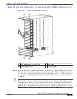
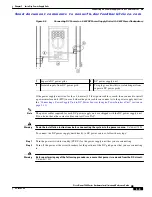
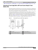
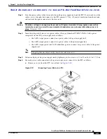
Connecting a DC Power Supply Unit to DC Power Sources
Step 3
Size the power cables to the distance between the power supply unit and the DC power grid. If you need
to cut the cable, cut it at the ends that connect to the DC power grid, remove 0.75 inch (19 mm) of
insulation from the cut ends, and attach them to the DC power system. Be sure to connect the negative
cables to negative lines and positive cables to positive lines. To determine which color of cables is
positive and which color is negative, see the polarity marked on the plug at the other end of the cable.
Note
If the 4.6-meter (15 foot) power cables are too short to connect the power supply unit to the
power source, you need to install a PIU within reach of the power supply unit (see the
Warning
Hazardous voltage or energy may be present on DC power terminals. Always replace cover when
terminals are not in service. Be sure uninsulated conductors are not accessible when cover is in
place.
Statement 1075
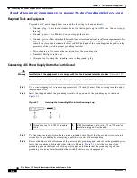
Step 4
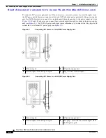
Connect one or two power cables (Cisco part number N7K-DC-CAB=) to the DC power supply unit and
the DC power grid. Each cable has one plug that connects two fully isolated 1.5 kW input modules to a
DC power supply for 3 kW of power. Depending on your power requirements, connect the cables as
follows:
–
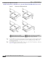
For 3 kW of output power, use one set of four cables and connect its two fully isolated input
modules to the DC power grid (see
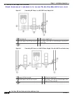
–
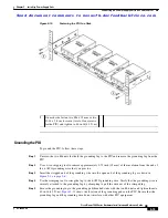
For 6 kW of output power, use two sets of four cables and connect their fully isolated input
modules to the same DC power grid (see
–
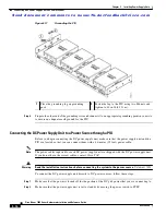
For 3 kW of output power and 3 kW of redundant power, use two sets of four cables and connect
each set of four cables to separate DC power grids (see
).
Note
For all your power connections, use one color cable for positive circuits and the other color for
negative circuits.
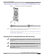
Step 5
Insert one or two power cable plugs into the DC power supply unit power receptacles. The cables are
keyed to fit one way only. If you cannot insert it easily in the receptacle, turn it over and reinsert it. When
fully inserted, fasten the plugs to the power supply unit by tightening their two screws to 8 to 11 in-lb
(0.9 to 1.2 N.m).
Step 6
For the powered down circuits connected to the power supply units, turn on the power at the circuit
breaker. The Input LEDs turn on as follows:
•
For 3 kW of power, either Input 1 and Input 2 LEDs will turn green or the Input 3 and Input 4 LEDs
will turn green.
•
For 6 kW of power, all four of the Input LEDs will turn green.
Step 7
Turn the power switch on the DC power supply unit from STBY to ON. The LEDs should flash and then
the Output LED should turn on in addition to the Input LEDs.
If the FAULT LED is lit or blinking, call Cisco TAC for assistance.


