background image

27


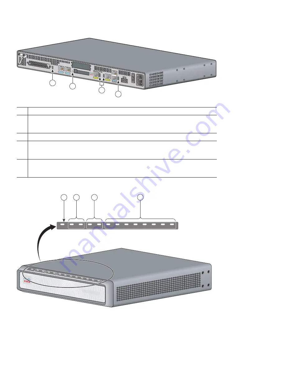
Figure 28

Cisco IAD2430 Series LEDs (Cisco 2432-24FXS shown)

Figure 29

Cisco IAD2435 Series LEDs

No.

LED/Color and Description

1

ACT—green: Green indicates activity—when any of the 24 voice ports is active in a call (off 
hook) or when one of the analog ports is in use
Status—green: Green when accessing IAD

2

CF (Slot 0)—green: Green when accessing read or write function

3

LINK—green: Indicates link activity
100—green: 100BASE-T is active
FDX—green: Green when full duplex is active, off when in half-duplex mode

4

ACT—green: Blinking green during packet transfer and interrupts
SYS—green: Blinking green for power-on and self-test, then solid green
PWR—green: Solid green when system has power

95007

1

2

4

3

Cisco IAD24

00 SERIES

OK

0/0

0/1

FE

T1/E1

FXS

CD

AL

2/0

2/1

2/2

2/3

2/4

2/5

2/6

2/7

272227

4

1

OK

0/0

0/1

FE

T1/E1

FXS

AL

CD

2/0

2/1

2/2

2/3

2/4

2/5

2/6

2/7

2

3

Summary of Contents for IAD2430 Series

Page 1: ...rranty Terms 2 Obtaining Documentation and Submitting a Service Request 3 Equipment Tools and Accessories 4 Product Serial Number Location 5 Accessibility 6 Safety Information 7 Installing the Chassis 8 Installing a WAN or Voice Interface Card 9 Connecting Cables 10 Powering On the Cisco IAD 11 Performing the Initial Configuration ...

Page 2: ...ll new and revised Cisco technical documentation at http www cisco com en US docs general whatsnew whatsnew html Subscribe to the What s New in Cisco Product Documentation as a Really Simple Syndication RSS feed and set content to be delivered directly to your desktop using a reader application The RSS feeds are a free service and Cisco currently supports RSS version 2 0 3 Equipment Tools and Acce...

Page 3: ...ls and features of the Cisco IAD2430 series models Figure 4 shows the back panel and features of the Cisco IAD2432 24FXS IAD model Figure 5 shows the back panel and features of the Cisco IAD2435 8FXS IAD model Note Not all models have all functions 88839 CISCO IAD2400 231872 Cisco IAD2400 SERIES OK 0 0 0 1 FE T1 E1 FXS CD AL 2 0 2 1 2 2 2 3 2 4 2 5 2 6 2 7 ...

Page 4: ...8FXS IAD RJ 21 analog voice interface T1 E1 ports 1 FE ports 1 WIC VIC option External flash memory Cisco IAD2431 16FXS IAD RJ 21 analog voice interface T1 E1 ports 1 FE ports 2 WIC VIC option External flash memory Cisco IAD2431 1T1E1 IAD T1 E1 ports 2 FE ports 2 WIC VIC option External flash memory 88838 VG224 24FXS 88825 IAD2431 8FXS 88826 IAD2431 16FXS 88827 IAD2431 1T1E1 ...

Page 5: ...y Cisco IAD2435 8FXS IAD RJ 21 analog voice port T1 E1 ports 1 FE ports 2 1 Chassis ground connection 2 RJ 21 connector 3 T1 E1 port 1 4 T1 E1 port 0 5 Flash memory port 6 WIC VIC slot 7 Fast Ethernet port 1 8 Fast Ethernet port 0 9 AUX port 10 Console port 11 DC power input 12 On off switch 13 AC power input 88824 231873 IAD2435 8FXS 12V DC SA CONSOLE AUX FastEthernet WAN 0 1 0 0 T1 E1 FXS 88828 ...

Page 6: ...uirements Items Included with Cisco IAD2435 IADs The following items are included with the Cisco IAD2435 IAD Connected RJ 45 to DB9 cable labeled Console Power cord 4 Product Serial Number Location The serial number label for most of the Cisco IAD2430 series routers is located on the bacj of the chassis at the bottom near the compliance label The serial number label for the Cisco IAD2435 integrate...

Page 7: ...e statement number provided at the end of each warning to locate its translation in the translated safety warnings that accompanied this device Statement 1071 SAVE THESE INSTRUCTIONS Warning Only trained and qualified personnel should be allowed to install or replace this equipment Statement 1030 Warning Do not work on the system or connect or disconnect cables during periods of lightning activity...

Page 8: ...sociated circuit board when the ringer is active The ringer is activated by an incoming call Statement 1042 Warning This equipment needs to be grounded Use a green and yellow 12 to 14 AWG ground wire to connect the host to earth ground during normal use Statement 242 Warning The importance of proper grounding cannot be overemphasized It will minimize the potential for damage to your system and max...

Page 9: ...ction authority or an electrician if you are uncertain that suitable grounding is available Statement 1024 Warning Use copper conductors only Statement 1025 Warning Blank faceplates and cover panels serve three important functions they prevent exposure to hazardous voltages and currents inside the chassis they contain electromagnetic interference EMI that might disrupt other equipment and they dir...

Page 10: ...ovides the procedures for installing the chassis Chassis Installation Options You can set the chassis on a desktop install it in a rack or mount it on a wall Tip Before proceeding consider the location of the equipment with respect to a good ground See the Grounding the Chassis section on page 18 See the following instructions Using the Correct Bracket Screws page 10 Using Rack Mount Brackets page...

Page 11: ...t attach the short leg of the bracket to the chassis at the pair of holes in the center of the chassis side See the Wall Mounting the Chassis section on page 13 Figure 6 Rack Mount Bracket Figure 7 shows the rack mount bracket for the Cisco IAD2435 8FXS model Figure 7 Rack Mount Bracket Cisco IAD2435 8FXS only Table 1 Bracket Attachment Screws for Rack Mounting and Wall Mounting Rack Mounting Wall...

Page 12: ...te Screws are included for attaching the brackets to the chassis but not for installing the chassis in a rack or on a wall You must purchase four additional machine screws to install the chassis in a rack Use the screw size required by your rack Caution Cisco IAD2435 8FXS provides for back panel rack mounting only as shown in Figure 11 Figure 8 19 Inch Rack Mounting with Front Panel Forward Figure...

Page 13: ...the chassis that weighs more than 10 lb 4 5 kg Excessive weight on top can damage the chassis Setting the Cisco IAD2435 on a Desktop You can also place the Cisco IAD2435 IAD on a desktop To place the Cisco IAD2435 IAD on a desktop follow the preceding steps Caution Do not place anything on top of the router that weighs more than 5 pounds 2 25 kg and do not stack routers on a desktop Excessive dist...

Page 14: ... the chassis Step 3 Attach the router to the wall by using the brackets and attachment hardware that you provide as follows You can install a starter screw in the wall and hook the bracket keyhole over the screw This holds the unit in place for easy installation of the attachment screws Attach both brackets to the wall Note For attaching to a wall stud each bracket requires two number 10 wood scre...

Page 15: ... number six 3 4 inch M3 5 x 20 mm screws You must provide the screws Figure 14 shows the mounting screw slots Caution If you are mounting the router on drywall use two hollow wall anchors 1 8 inch with 5 16 inch drill bit or M3 with 8 mm drill bit to secure the screws If the screws are not properly anchored the strain of the network cable connections could pull the router from the wall 1 Wall 2 Br...

Page 16: ...upply must rest on a horizontal surface such as the floor or a table If the power supply is not supported it could place strain on the power supply cable and cause it to disconnect from the connector on the router back panel To wall mount a Cisco IAD2435 IAD follow these steps Step 1 Secure two screws 7 inches 17 78 centimeters apart into a wall and 5 32 inch 0 40 centimeter from the wall Step 2 H...

Page 17: ...stance between the two screws 7 in 17 78 cm 3 Cisco IAD2435 router 4 Mounting screw slots 5 Maximum distance between the router and the power supply 6 ft 1 8 m 6 Horizontal surface for supporting the power supply 7 Distance between the screw and the wall 5 32 in 0 40 cm 231985 1 5 6 4 2 7 3 ...

Page 18: ... tap between the ground of a junction box and a metal water pipe between the Cisco IAD chassis and the ground of a power tap and between the Cisco IAD chassis and the ground of a junction box A good ground connection should read between 0 0 and 0 5 ohm Step 2 Strip one end of the ground wire to the length required for the ground lug or terminal For the NEBS ground lug approximately 0 75 inch 20 mm...

Page 19: ... card WIC or voice interface card VIC Note The Cisco IAD2435 router is a fixed configuration router and does not support interface cards Releases of the Cisco IAD2430 series IADs support the following WICs and VICs also used by Cisco 2600 series and Cisco 3600 series routers WIC 1T WIC 2T WIC 1DSU T1 VIC2 2FXS VIC2 4FXS VIC2 2FXO VIC2 4FXO VIC2 2BRI NT TE WIC 1ADSL WIC 1SHDSL V2 WIC 1ADSL DG 1 Gro...

Page 20: ...co IAD Step 4 Use the screwdriver to tighten the captive screws on the card 9 Connecting Cables This section provides the procedure for connecting cables to your router Connecting LAN and Power Cables Table 2 lists port connections and cables for connecting Cisco IAD2430 series routers Figure 19 shows LAN administrative access and power connections for the Cisco IAD2430 series IADs Figure 20 shows...

Page 21: ...le port 3 AUX port 4 Fast Ethernet straight through 5 RJ 45 to DB9 console cable 6 RJ 45 to DB25 auxiliary cable 1 Fast Ethernet port 2 Serial port console or auxiliary 3 Fast Ethernet straight through 4 RJ 45 to DB9 console cable 88845 4 5 6 Ethernet hub 1 2 3 Cisco IAD2430 series Modem PC 232070 IAD2435 8FXS 12V DC SA CONSOLE AUX FastEthernet WAN 0 1 0 0 T1 E1 FXS 1 Ethernet hub PC 3 4 2 ...

Page 22: ... is initially set to 800 Ohms then adjusts to 50 Ohms when ringing voltage is not present Table 3 WAN and Voice Cable Selection Port or Interface Color or Type Connected To Cable not included T1 E1 WIC 1DSU T1 WAN Light green WAN RJ 48 T1 cable T1 E1 Digital voice RJ 48C Digital PBX RJ 48 T1 cable WIC 2T Serial 60 pin D sub CSU DSU and serial network or equipment Serial transition cable matching s...

Page 23: ...gure 22 Cisco IAD2430 Series RJ 21 Velcro Harness Step 1 Slip the RJ 21 cable connector through the Velcro strap see Figure 23 Figure 23 Sliding the RJ 21 Cable Through the Velcro Harness Step 2 Push the male RJ 21 cable connector into the slot of the female RJ 21 connection on the router Push the male RJ 21 cable firmly until the RJ 21 security clips are firmly seated see Figure 24 281199 IAD2435...

Page 24: ...screws on the RJ 21 male connector see Figure 25 Figure 25 Tightening the Captive Screws Step 4 Pull the Velcro strap up until it is tight Then pull it down and affix the strap to the other side of the Velcro harness see Figure 26 281201 IAD2435 8FXS FastEthernet WAN 0 1 0 0 T1 E1 FXS 281202 IAD2435 8FXS FastEthernet WAN 0 1 0 0 T1 E1 FXS ...

Page 25: ...e to power on your Cisco IAD2430 series IADs and verify that it completes its initialization and self test To power on the Cisco IAD follow these steps Step 1 Power on your terminal or PC and configure it for 9600 bps 8 data bits 1 stop bit and no parity Step 2 Move the Cisco IAD power switch to the ON position Cisco IAD2430 through Cisco IAD2432 IADs only The green LED next to the auxiliary AUX p...

Page 26: ...rminate autoinstall and continue with manual configuration Several messages appear ending with lines similar to the following Copyright c 2008 by cisco Systems Inc Compiled date time by person Step 5 Press Return to bring up the Router prompt flashfs 4 Initialization complete Router Step 6 Enter privileged EXEC mode Router enable Router Step 7 Continue with the Performing the Initial Configuration...

Page 27: ... when accessing read or write function 3 LINK green Indicates link activity 100 green 100BASE T is active FDX green Green when full duplex is active off when in half duplex mode 4 ACT green Blinking green during packet transfer and interrupts SYS green Blinking green for power on and self test then solid green PWR green Solid green when system has power 95007 1 2 4 3 Cisco IAD2400 SERIES OK 0 0 0 ...

Page 28: ...e these publicly known initial credentials using Cisco CP Express or the Cisco IOS CLI Here are the Cisco IOS commands username myuser privilege 15 secret 0 mypassword no username cisco Replace myuser and mypassword with the username and password you want to use For more information about Cisco CP Express please follow the instructions in the QUICK START GUIDE for your router User Access Verificat...

Page 29: ...ttings by using the setup command facility follow these steps Step 1 Establish a console connection to your router and enter privileged EXEC mode For instructions on how to enter privileged EXEC mode see Step 1 through Step 4 in the Cisco IOS CLI section on page 28 Step 2 In privileged EXEC mode at the prompt enter setup yourname setup The following message is displayed System Configuration Dialog...

Page 30: ...port The virtual terminal password is used to protect access to the router over a network interface Enter virtual terminal password xxxxxx Step 9 Respond to the following prompts as appropriate for your network Configure SNMP Network Management yes Community string public A summary of the available interfaces is displayed Step 10 Choose one of the available interfaces for connecting the router to ...

Page 31: ...ss To set an IP address for the Fast Ethernet port follow the steps below After setting this address you can configure the Cisco IAD2430 series IADs remotely through a Telnet connection Configuring a T1 E1 Port for a WAN Connection The T1 E1 port supports balanced T1 E1 according to ANSI T1 403 and has a built in CSU DSU Command Description Step 1 Router configure terminal Enters global configurat...

Page 32: ...rt 133 266 399 533 655 or Router config ctrl cablelength long gain26 gain36 15db 22 5db 7 5db 0db Configures the cable length if the length is 655 ft 200 m or shorter or Configures the receive gain and transmit attenuation if the cable length is longer than 655 ft 200 m Step 5 Router config ctrl framing sf esf If necessary changes the DS1 link framing format The default is SuperFrame sf Step 6 Rou...

Page 33: ...a T1 E1 interface Note Configure a maximum of 8 time slots in a DS0 group on the Cisco IAD2435 IAD Step 8 Router config ctrl no shutdown Activates the T1 E1 controller Step 9 Router config ctrl exit Exits controller configuration mode Step 10 Router config exit Exits configuration mode Step 11 Router show controller t1 e1 1 0 Verifies the controller configuration Command Description Router show ru...

Page 34: ...apore Europe Headquarters Cisco Systems International BV Amsterdam The Netherlands Cisco has more than 200 offices worldwide Addresses phone numbers and fax numbers are listed on the Cisco Website at www cisco com go offices Printed in the USA on recycled paper containing 10 postconsumer waste 78 15666 02 B0 ...

Reviews: