


31
Cisco 1721, 1760, 2621XM, 2651XM, 2691, 3725, and 3745 Modular Access Routers and 7206-VXR NPE-400 Router FIPS 140-2 Non-Proprietary
OL-6083-01
The Cisco 1721, 1760, 2621XM, 2651XM, 2691, 3725, 3745, and 7206 VXR NPE-400 Routers
Step 5
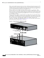
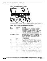
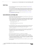
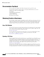
Place the fourth label on the router as shown in
Figure 21
. The tamper evidence label should be placed
so that the half of the label covers the enclosure and the other half covers the WAN interface card slot.
Any attempt to remove a WAN interface card will leave tamper evidence.
Step 6
Place the fifth label on the router as shown in
Figure 21
. The tamper evidence label should be placed so
that one half of the label covers the enclosure and the other half covers the WAN interface card slot. Any
attempt to remove a WAN interface card will leave tamper evidence.
Step 7
The labels completely cure within five minutes.
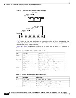
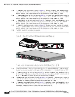
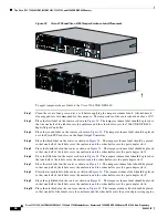
Figure 21
Cisco 2621XM and Cisco 2651XM Tamper Evidence Label Placement
To apply serialized tamper-evidence labels to the Cisco 2691:
Step 1
Clean the cover of any grease, dirt, or oil before applying the tamper evidence labels. Alcohol-based
cleaning pads are recommended for this purpose. The temperature of the router should be above 10°C.
Step 2
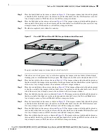
Place the first label on the router as shown in
Figure 22
. The tamper evidence label should be placed so
that the one half of the tamper evidence label covers the enclosure and the other half covers the right side
of the router. Any attempt to remove the enclosure will leave tamper evidence.
Step 3
Place the second label on the router as shown in
Figure 22
. The tamper evidence label should be placed
so that the one half of the tamper evidence label covers the enclosure and the other half covers the left
side of the router. Any attempt to remove the enclosure will leave tamper evidence.
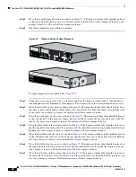
Step 4
Place the third label on the router as shown in
Figure 22
. The tamper evidence label should be placed so
that the one half of the label covers the enclosure and the other half covers the Network Module slot.
Any attempt to remove a Network Module will leave tamper evidence.
Step 5
Place the fourth label on the router as shown in
Figure 22
. The tamper evidence label should be placed
so that the half of the label covers the enclosure and the other half covers the left WAN interface card
slot. Any attempt to remove a WAN interface card will leave tamper evidence.
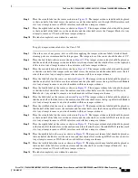
Step 6
Place the fifth label on the router as shown in
Figure 22
. The tamper evidence label should be placed so
that one half of the label covers the enclosure and the other half covers the middle WAN interface card
slot. Any attempt to remove a WAN interface card will leave tamper evidence.
Step 7
Place the sixth label on the router as shown in
Figure 22
. The tamper evidence label should be placed so
that one half of the label covers the enclosure and the other half covers the right WAN interface card slot.
Any attempt to remove a WAN interface card will leave tamper evidence.
99498
SEE MANUAL BEFORE INSTALLATION
SERIAL 1
SERIAL 0
CONN
CONN
WIC
2A/S
SEE MANUAL BEFORE INSTALLATION
SERIAL 1
SERIAL 0
CONN
CONN
WIC
2T
Cisco 2611
100-240V– 1A
50/60 Hz 47 W
W0
AUX
CONSOLE
ETHERNET 0 ACT
LINK
ACT
ETHERNET 1
LINK
W1
POWER
RPS
ACTIVITY
Cisco 2600
SERIES


