background image

BLACK BOX

®

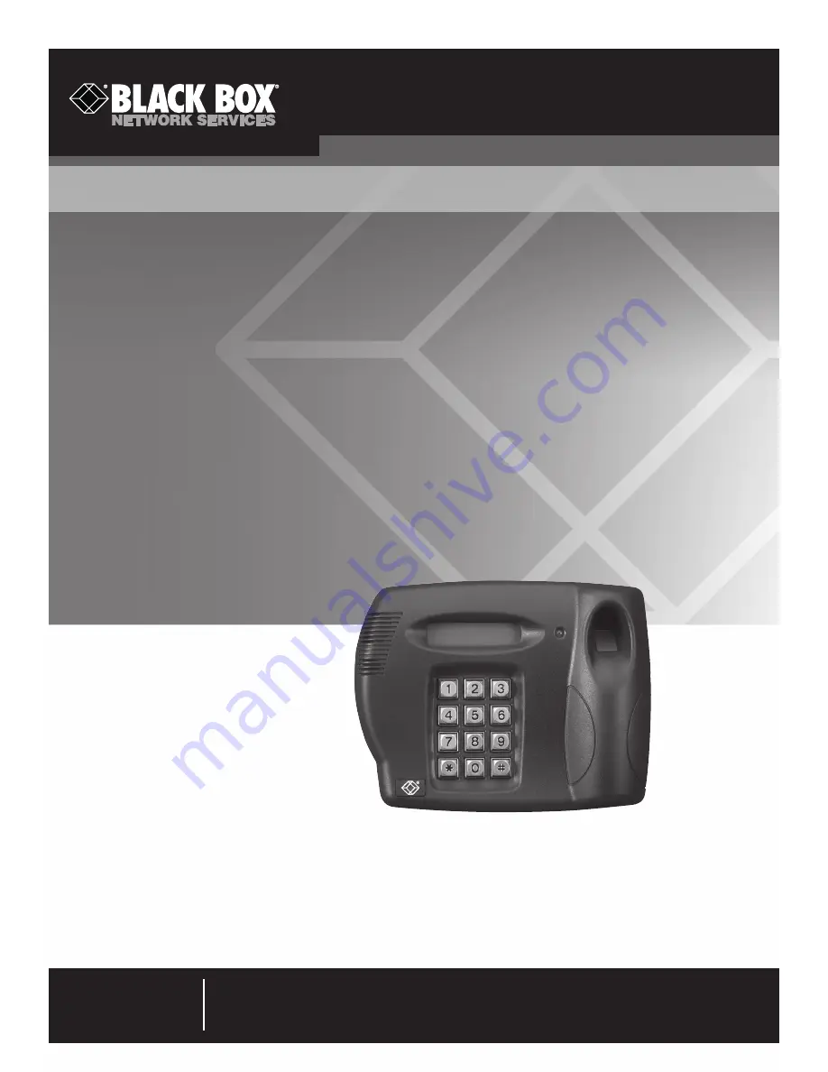
Featuring enhanced biometric security with two-

factor authentication, providing the perfect blend 

of security and simplicity.

Intelli-Pass™


Quick-Start Guide

Order toll-free in the U.S.: Call 877-877-BBOX (outside U.S. call 724-746-5500)

FREE technical support 24 hours a day, 7 days a week: Call 724-746-5500 or fax 724-746-0746

Mailing address: Black Box Corporation, 1000 Park Drive, Lawrence, PA 15055-1018

Web site: www.blackbox.com   •   E-mail: [email protected]

Customer 

Support 

Information

August 2009


SAC510NA

SAC510SA

SAC500MSA

Summary of Contents for SAC500MSA

Page 1: ...de Order toll free in the U S Call 877 877 BBOX outside U S call 724 746 5500 FREE technical support 24 hours a day 7 days a week Call 724 746 5500 or fax 724 746 0746 Mailing address Black Box Corporation 1000 Park Drive Lawrence PA 15055 1018 Web site www blackbox com E mail info blackbox com Customer Support Information August 2009 SAC510NA SAC510SA SAC500MSA ...

Page 2: ...ark of BB Technologies Inc Any other trademarks mentioned in this manual are acknowledged to be the property of the trademark owners We re here to help If you have any questions about your application or our products contact Black Box Tech Support at 724 746 5500 or go to blackbox com and click on Talk to Black Box You ll be live with one of our technical experts in less than 20 seconds ...

Page 3: ...operated in a commercial environment Operation of this equipment in a residential area is likely to cause interference in which case the user at his own expense will be required to take whatever measures may be necessary to correct the interference Changes or modifications not expressly approved by the party responsible for compliance could void the user s authority to oper ate the equipment This ...

Page 4: ...ue impidan el flujo de aire por los orificios de ventilación 10 El equipo eléctrico deber ser situado fuera del alcance de fuentes de calor como radiadores registros de calor estufas u otros aparatos incluyendo amplificadores que producen calor 11 El aparato eléctrico deberá ser connectado a una fuente de poder sólo del tipo descrito en el instructivo de operación o como se indique en el aparato 1...

Page 5: ...nit 13 3 5 1 Fail Safe Locks and Magnetic Locks 12V 13 3 5 2 Fail Secure Locks 12V 14 3 5 3 Fail Safe Locks and Magnetic Locks 24V 14 3 5 4 Fail Secure Locks 24V 15 3 6 Request to Exit RTE Switch 15 3 7 Door Sensor 16 3 8 Fire Panel Integration 18 3 9 Alarm Output 19 3 10 Wiegand Output 26 bit Protocol 21 3 11 Network Connection 22 3 12 Powering On the Unit 22 4 Software Setup 23 4 1 Factory Defau...

Page 6: ...e 8 hours Encryption Proprietary algorithm head unit to controller communications User Controls 12 digit keypad LCD menu Power Input 100 240 VAC 50 60 Hz Output 18 5 VDC 3 5 amps 65 watts Size Control Unit 10 5 H x 10 3 W x 4 D 26 7 x 26 2 x 10 2 cm Head Unit 5 8 H x 7 5 W x 2 4 D 14 6 x 19 1 x 6 cm ...

Page 7: ...ftware The Intelli Pass consists of two components a head unit and a control unit The head unit has two parts a front section and a back section and mounts on a wall next to the door you want to control You can place the control unit above a false ceiling or high up out of general reach since you will not need to access it once you install the Intell Pass system This user s manual describes how to...

Page 8: ...1 shows the Intelli Pass head unit s front section 2 line LCD display Fingerprint scanner area Keypad Figure 2 1 Head unit s front section 2 4 Head Unit Back Section Figure 2 2 illustrates the Intelli Pass head unit s back section Mounting holes Cable passageway Figure 2 2 Head unit s back section t ea ...

Page 9: ...Page 9 Chapter 2 Overview 2 5 Control Unit Figure 2 3 illustrates the control unit Figure 2 3 Control unit ...

Page 10: ...bottom right with a pencil on the wall 3 Drill and plug where necessary the wall where you will install four mounting screws 4 Drill through the wall where you have marked the cable passageway Leave enough room so that the cable can pass directly into the rear of the unit 5 Mount the back plate of the head unit to the wall using screws appropriate for the surface being fastened to screws not inclu...

Page 11: ...e rear of the head unit Leave approximately 12 300 mm of spare cable at each end so that you can strip the wires and connect them to the terminal blocks 3 The cable should be wired as shown in Figure 3 1 The actual colors are not important but make sure you connect each pair of wires as shown in the diagram 4 Wire the head unit as shown in Figure 3 1 5 To simplify the wiring you can remove the 2 p...

Page 12: ...power supply you received from Black Box to power the control unit or an exact equivalent 1 Strip approximately 1 4 6 mm of plastic sheath from each cable to the power supply and connect to the appropriate terminal blocks checking that all wires are securely fastened 2 If you previously removed the battery as recommended reinstall it and fasten securely 3 Reconnect the battery as shown in Figure 3...

Page 13: ... unit 3 5 1 Fail Safe Locks and Magnetic Locks 12V A fail safe or magnetic lock has a permanent 12V supply to keep the lock closed 1 Connect the Ground Lead of the lock to a terminal labeled GND 2 Connect the Live Lead of the lock to the terminal labeled SOL 3 Connect a link between Link and NC and a link between COM and 12V Figure 3 4 Fail safe or magnetic locks 12V door controls Chapter 3 Instal...

Page 14: ...labeled SOL 3 Connect a link between Link and NO and a link between COM and 12V Figure 3 5 Fail secure lock 12V door controls 3 5 3 Fail Safe Locks and Magnetic Locks 24V A fail safe or magnetic lock has a permanent 24V supply to keep the lock closed The Intelli Pass controller does not supply a 24V output To use a 24V lock you will need a separate power supply Wire a 24V fail safe lock as shown i...

Page 15: ...eed a separate power supply Wire a 24V fail secure lock as shown in Figure 3 7 Figure 3 7 Fail secure locks 24V door controls 3 6 Request to Exit RTE Switch The control unit has a built in delay for the RTE switch Connect a push switch as shown in Figure 3 8 The exit delay is set through the PC software on a networked unit or through the menus on the head unit for a standalone v Figure 3 8 Request...

Page 16: ...ure 3 9 Figure 3 9 Door sensor The door sensor circuit provides a feature to work with a special type of door sensor that is tamper proof This prevents an internal security breach where someone with authorized access to an area could potentially short out the contacts on the door sensor If you re using it with the anti tamper door sensors set the SW SEL JMP1 jumper as follows Figure 3 10 Tamper pr...

Page 17: ...igure 3 11 Jumper settings when used with a normal door sensor Figure 3 12 Jumper settings when used with an anti tamper door sensor If you aren t using the door sensor keep the link in place as shown in Figure 3 13 Figure 3 13 Door sensor not used ...

Page 18: ...see Figure 3 14 to reset the unit manually Doors will remain unlocked until you reset the unit 2 Figure 3 14 shows how to connect a control unit to a fire panel Connect the unit to either a normally open or normally closed set of contacts as shown in Figures 3 14 and 3 15 Figure 3 14 Connect the control unit to the fire panel 3 Only remove the link between 0V and NC if the system is wired as follo...

Page 19: ...ut Certain conditions that occur on the unit will cause the Alarm Relay to operate The Alarm Relay can be used to connect the control unit to a third party system When one of the following conditions happens the Intelli Pass alerts the third party system The following will send an alarm alert Tampering detected on the head unit A forced door A door being propped open The duress feature is activate...

Page 20: ...724 746 5500 blackbox com Page 20 Intelli Pass Quick Start Guide Figure 3 18 Alarm input relay connected Figure 3 19 Alarm panel relay not connected ...

Page 21: ... 3 20 Using the alarm relay to power a third party buzzer or siren 3 10 Wiegand Output 26 bit Protocol The Intelli Pass controller offers a 26 bit Wiegand output for seamless integration into a third party access control system Figure 3 21 shows how to connect a control unit to a third party system Figure 3 21 Connecting a control unit to a third party system Page 21 ...

Page 22: ...hat the supply is switched on 2 The unit should now power on If not unplug the unit and check all wiring 3 The buzzer on the control unit should sound for one second 4 Check the LCD display 5 If the display reads LCD CONTRAST 0 9 0 DONE the unit is OK 6 If the unit does not get to this stage or displays a different message make sure the cable between the head unit and control unit is wired correct...

Page 23: ...n the setup menu you can press to return to a previous option When you need to enter a numeric value the current value is displayed and the prompt message gives the number of digits you must enter Enter the new value or press to keep the current value If you make a mistake while entering numbers press to go back to the start of the line If you press at the start of a line the system goes back to t...

Page 24: ...purposes The following messages will be displayed on the Head Unit LCD ENROLL MANAGERS 1 second delay NEW MANAGER ENTER ID 0001 1 second delay PLACE FINGER KEY 1 WHEN READY 5 Once the finger is placed on the scanner ensuring that the finger is flat and straight press 1 on the Head Unit keypad After about 4 5 seconds the Head Unit displays PRINT STORED REMOVE FINGER 6 Remove the finger from the fin...

Page 25: ...ead Unit will then display PLACE FINGER ON SCANNER 11 Place the same finger on the scanner to verify the enrollment 12 The Head Unit will then display PRINT VERIFIED REMOVE FINGER 1 second delay SETUP COMPLETE 1 second delay 01 01 01 00 00 ENTER ID _ The initial setup is now complete NOTE The date and time will be incorrect These are set via the PC based management software The first enrolled fing...

Page 26: ...IN 3 Place the appropriate finger on the Head Units fingerprint scanner Once in the menu the only option available is LCD CONTRAST 0 9 0 DONE 4 Using the keypad on the Head Unit type in a value 0 thru 9 to set your preferred contrast for the LCD display You will see the contrast change as you select each value If the chosen contrast is not correct keep entering new values until you select the desi...

Page 27: ...u do make a record of the history of the problem We will be able to provide more efficient and accurate assistance if you have a complete description including the nature and duration of the problem when the problem occurs the components involved in the problem any particular application that when used appears to create the problem or make it worse 6 3 Shipping and Packaging If you need to transpo...

Page 28: ...724 746 5500 blackbox com Page 28 Intelli Pass Quick Start Guide Appendix A Head Alignment Template ...

Page 29: ...Page 29 Appendix B Software Flowcharts Appendix B Software Flowcharts Figure B 1 Menu map ...

Page 30: ...724 746 5500 blackbox com Page 30 Intelli Pass Quick Start Guide Figure B 2 User data menu map ...

Page 31: ...Page 31 Appendix B Software Flowcharts Figure B 3 System data menu map ...

Page 32: ...ng from cabinets and racks and power and surge protection products to media converters and Ethernet switches all supported by free live 24 7 Tech support available in 20 seconds or less Copyright 2009 All rights reserved Black Box Tech Support FREE Live 24 7 Tech support the way it should be Great tech support is just 20 seconds away at 724 746 5500 or blackbox com ...

Reviews: