


34
Cisco 1721, 1760, 2621XM, 2651XM, 2691, 3725, and 3745 Modular Access Routers and 7206-VXR NPE-400 Router FIPS 140-2 Non-Proprietary
OL-6083-01
The Cisco 1721, 1760, 2621XM, 2651XM, 2691, 3725, 3745, and 7206 VXR NPE-400 Routers
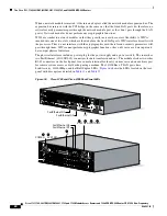
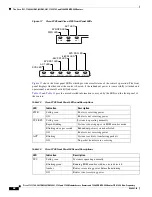
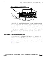
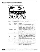
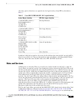
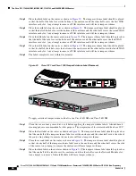
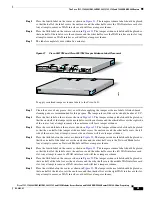
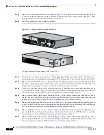
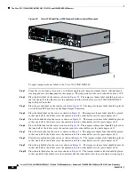
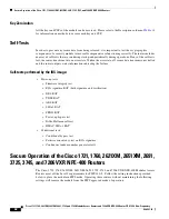
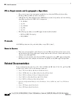
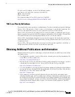
Figure 23
Cisco 3725 and Cisco 3745 Tamper Evidence Label Placement
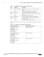
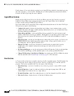
To apply tamper-evidence labels to the Cisco 7206 VXR NPE-400:
Step 1
Clean the cover of any grease, dirt, or oil before applying the tamper evidence labels. Alcohol-based
cleaning pads are recommended for this purpose. The temperature of the router should be above 10°C.
Step 2
Place the first label on the router as shown in
Figure 24
. The tamper evidence label should be placed so
that the one half of the label covers the enclosure and the other half covers the 7206 VXR NPE-400
Input/Output Controller.
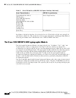
Step 3
Place the second label on the router as shown in
Figure 24
. The tamper evidence label should be placed
over the Flash PC Card slots on the Input/Output Controller.
Step 4
Place the third label on the router as shown in
Figure 24
. The tamper evidence label should be placed
so that one half of the label covers the enclosure and the other half covers the port adapter slot 1.
Step 5
Place the fourth label on the router as shown in
Figure 24
. The tamper evidence label should be placed
so that one half of the label covers the enclosure and the other half covers the port adapter slot 2.
Step 6
Place the fifth label on the router as shown in
Figure 24
. The tamper evidence label should be placed so
that one half of the label covers the enclosure and the other half covers the port adapter slot 3.
Step 7
Place the sixth label on the router as shown in
Figure 24
. The tamper evidence label should be placed
so that one half of the label covers the enclosure and the other half covers the port adapter slot 4.
Step 8
Place the seventh label on the router as shown in
Figure 24
. The tamper evidence label should be placed
so that one half of the label covers the enclosure and the other half covers the port adapter slot 5.
Step 9
Place the eighth label on the router as shown in
Figure 24
. The tamper evidence label should be placed
so that one half of the label covers the enclosure and the other half covers the port adapter slot 6.
Step 10
Place the ninth label on the router as shown in
Figure 24
. The tamper evidence label should be placed
so that one half of the label covers the enclosure and the other half covers the network processing engine.
SEE MANU
AL BEFORE INST
ALLATION
AL
CD
LP
RD
TD
SEE MANU
AL BEFORE INST
ALLATION
DSU
56K
AL
CD
LP
RD
TD
SEE MANU
AL BEFORE INST
ALLATION
DSU
56K
EN
V0
BANK 4
BANK 3
BANK 2
BANK 1
BANK 0
NM-HDV
VWIC
2MFT-E1
SEE
MANUAL
BEFORE
INSTALLAT
ION
CTRLR E2
CTRLR E1
AL
LP
CD
99508
EN
V0
BANK 4
BANK 3
BANK 2
BANK 1
BANK 0
NM-HDV
VWIC
2MFT-E1
SEE
MANUAL
BEFORE
INSTALLA
TION
CTRLR E2
CTRLR E1
AL
LP
CD
EN
V0
BANK 4
BANK 3
BANK 2
BANK 1
BANK 0
NM-HDV
VWIC
2MFT-E1
SEE
MANUAL
BEFORE
INSTALLA
TION
CTRLR E2
CTRLR E1
AL
LP
CD
EN
V0
BANK 4
BANK 3
BANK 2
BANK 1
BANK 0
NM-HDV
VWIC
2MFT-E1
SEE
MANUAL
BEFORE
INSTALLA
TION
CTRLR E2
CTRLR E1
AL
LP
CD
EN
V0
BANK 4
BANK 3
BANK 2
BANK 1
BANK 0
NM-HDV
VWIC
2MFT-E1
SEE
MANUAL
BEFORE
INSTALLA
TION
CTRLR E2
CTRLR E1
AL
LP
CD
SEE MAN
UAL BEFO
RE INSTA
LLATION
SERIAL 1
SERIAL 0
CONN
CONN
WIC
2T
SEE MAN
UAL BEFO
RE INSTA
LLATION
SERIAL 1
SERIAL 0
CONN
CONN
WIC
2T
SEE MAN
UAL BEFO
RE INSTA
LLATION
DSU
56K
C
D
A
L
L
P
R
D
TD


